
Hombre XS Space Cab L4-2.2L CPC (1997)
Fuel Pressure Regulator
REMOVAL PROCEDURE
WARNING: Relieve the fuel system pressure before servicing fuel system components in order to reduce the flak of fire and personal
injury. After relieving the system pressure, a small amount of fuel may be released when servicing the fuel lines or connections. In order
to reduce the chance of personal injury, cover the regulator and the fuel line fittings with a shop towel before disconnecting. This will
catch any fuel that may leak out Place the towel in an approved container when the disconnection is complete.
1. Relieve the fuel system pressure. Refer to Fuel Pressure Release Procedure.
2. Disconnect the negative battery cable.
3. Remove vacuum hose from regulator.
4. Remove the fuel return pipe clamp.
5. Remove the fuel return pipe and the O-ring from the regulator.
6. Discard the O-ring.
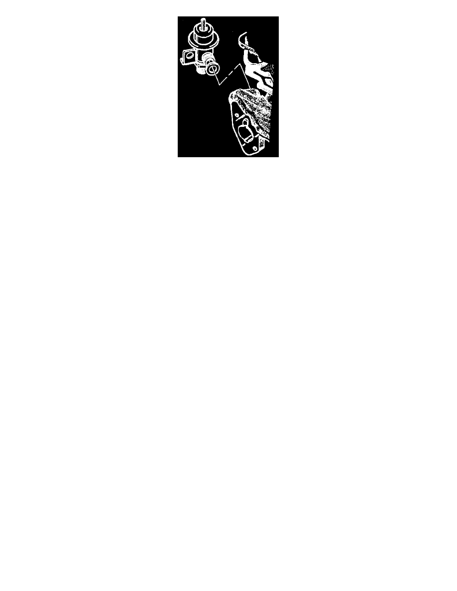
7. Remove the pressure regulator bracket attaching screw.
8. Remove the pressure regulator assembly.
9. Remove the O-ring.
10. Discard the O-ring.
11. If reinstalling the fuel pressure regulator, inspect the filter screen if equipped for contamination.
12. If contaminated, replace the filter screen.
Thread-locking Compound
NOTE: In precoating screws, do not use a higher strength locking compound than recommended. Doing so could make removing the screw
extremely difficult or result in damaging the screw head. The service repair kits are supplied with a small vial of thread-locking compound with
directions for use. If the material is not available, use Loctite 262 or the equivalent. Do not use a cleaner that contains methyl ethyl ketone, an
extremely strong solvent, and not necessary for this type of deposit. The throttle body metal parts may be cleaned following the disassembly in a
cold immersion-type cleaner such as GM X-55 or the equivalent.
CAUTION: Do not immerse the TP sensor and IAC valve in any type of cleaner because they are electronic devices.
INSTALLATION PROCEDURE
1. After lubricating the new pressure regulator O-ring with clean engine oil, install on the pressure regulator.
2. Install the pressure regulator assembly onto the manifold.
3. Install the pressure regulator bracket attaching screw coated with the appropriate thread-locking material.
Tighten
^
Tighten the pressure regulator bracket attaching screw to 3.5 Nm (31 lb. in.).
4. Install the vacuum hose to the regulator.
5. After lubricating the new fuel return pipe O-ring with clean engine oil, install on the end of pipe.
6. Install the fuel return pipe to pressure regulator.
Tighten
^
Tighten the fuel return pipe attaching nut to 3.0 Nm (22 lb. in).
7. Install the fuel return pipe clamp attaching nut to the lower manifold assembly.