
Hombre XS Space Cab L4-2.2L CPC (1997)
Pinion Flange: Testing and Inspection
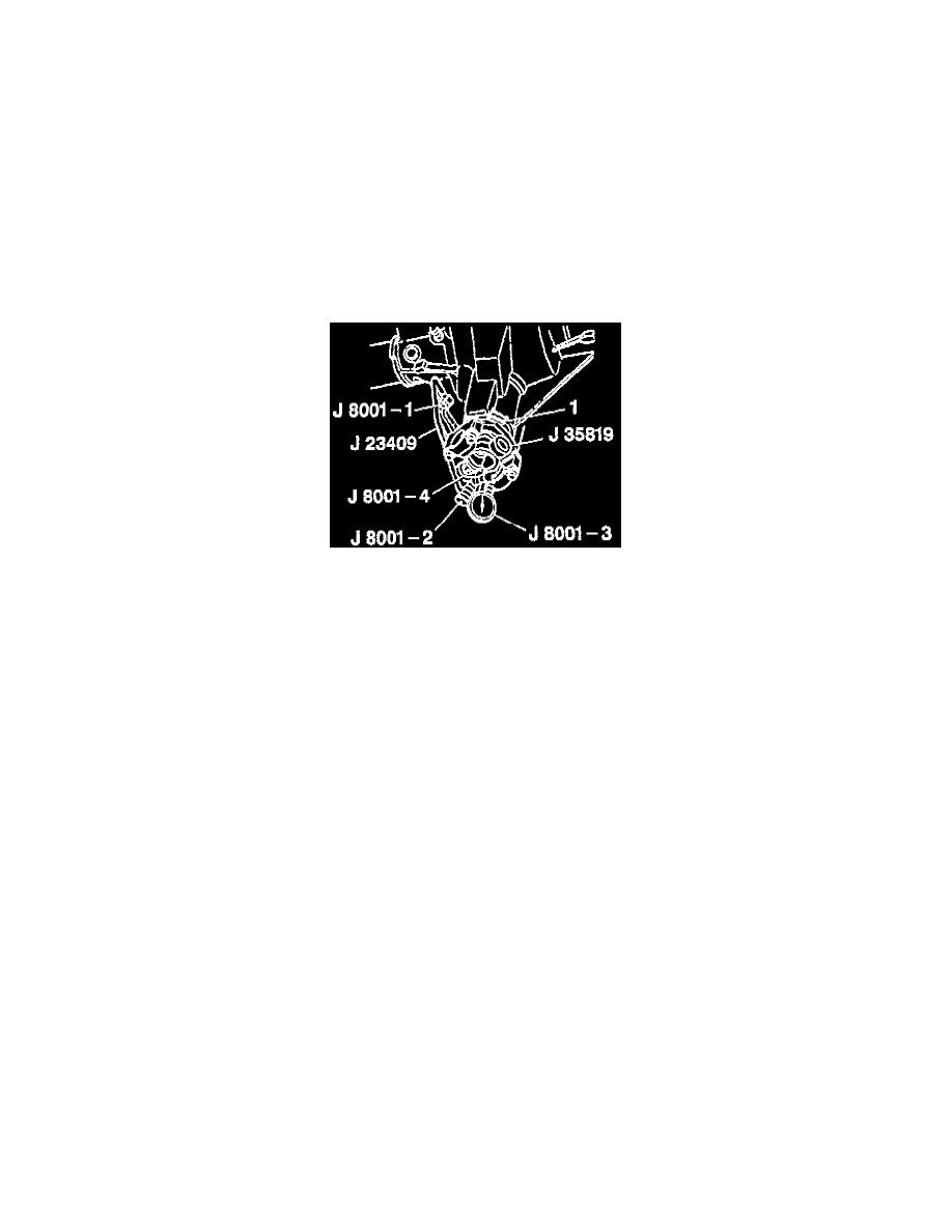
Tools Required
J 35819 Pinion Flange Runout Gauge
J 23409 Dial Indicator Extension
J 8001 Dial Indicator Set
1. Place the vehicle on a hoist, allowing free rotation of the rear wheels.
IMPORTANT: It is essential that the positions of all driveline components relative to the propeller shaft and axles be accurately reference
marked prior to disassembly. These components include the propeller shafts, drive axles, pinion flanges output shafts, etc. All components must be
reassembled in the exact relationship to each other as they were when removed. Specifications and torque values, as well as any measurements
made prior to disassembly, must be followed.
2. Remove the propeller shaft from the pinion flange.
-
Secure the propeller shaft up and out of the way so as not to put unnecessary stress on the universal joints.
3. Install J 35819 and J 8001 or equivalent.
-
After setup, set the dial indicator back to zero.
4. Rotate the pinion flange 360°. Record the highest and lowest readings and add them together. At the points of greatest deflection (highest and
lowest), mark the pinion flange at the dial indicator tab.
5. If pinion flange runout is 0.15 mm (0.006 inch) or less, no further action is required.
6. If pinion flange runout is over 0.15 mm (0.006 inch) but no greater than 0.38 mm (0.015 inch) and balance weight is at or near the low point of
pinion flange runout indicator reading, no further action is required.
-
If balance weight is not at or near the low point of pinion flange runout, remove the weight. Reindex the pinion flange until runout is 0.25 mm
(0.010 inch) or less.
-
If it is impossible to achieve 0.25 mm (0.010 inch) or less runout, install a new pinion flange and recheck for 0.25 mm (0.010 inch) or less
runout. Service replacement pinion flanges are not equipped with balance weights and no weights should be added.