
Hombre XS Space Cab L4-2.2L CPC (1997)
Drive/Propeller Shaft: Testing and Inspection
Balance Check
IMPORTANT: Never vent or fill the propeller shaft with an aerosol foam product. This will cause an excessive imbalance condition.
Remove Or Disconnect
In order to get an accurate check it is necessary to lift the vehicle by the axle or suspension to duplicate actual conditions. By doing this, the pinion
angle will be as close as possible to normal.
1. Tire and wheel assemblies.
2. Brake drums.
Inspect
^
Propeller shaft, universal joints, and attachments for mud, undercoating, or loose fasteners.
Clean
^
Propeller shaft, universal joints, and attachments.
Tighten
^
Any loose attachments or fasteners.
CAUTION: Do not spin the drive wheels faster than 55 km/h (35 mph) as indicated by the speedometer. This limit is necessary because
the speedometer indicates only one-half of the actual wheel speed when one drive wheel is spinning and the other drive wheel is stopped.
Personal injury and damage may result from high speed spinning.
IMPORTANT:
-
All persons should stay clear of universal joints and balance weight areas to avoid possible injury. Do not run the vehicle on the hoist for
extended periods due to the danger of overheating the transmission or engine.
-
Run the vehicle in gear at the speed where the disturbance peaks; observe the intensity of the disturbance.
NOTICE: Do not apply the brakes with the drums removed or damage to the brake shoes and attaching components could result.
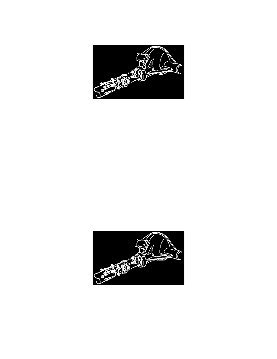
3. Bolts from propeller shaft.
IMPORTANT: It is essential that the positions of all driveline components relative to the propeller shaft and axles be observed and accurately
reference marked prior to disassembly. These components include the propeller shafts, drive axles, pinion flanges, output shafts, etc. All
components must be reassembled in the exact relationship to each other as they were when removed. Specifications and torque values, as well as
any measurements made prior to disassembly, must be followed.
4. Retainers.
5. Propeller shaft.
-
Rotate the propeller shaft 180° from the original position.