
Hombre XS Space Cab L4-2.2L CPC (1997)
2. Connect one lead of a self-powered test light or ohmmeter to one end of the part of the circuit you wish to test.
3. Connect the other lead to the other end of the circuit.
4. If the self-powered test light glows, there is continuity. When using an ohmmeter, low or no resistance means good continuity.
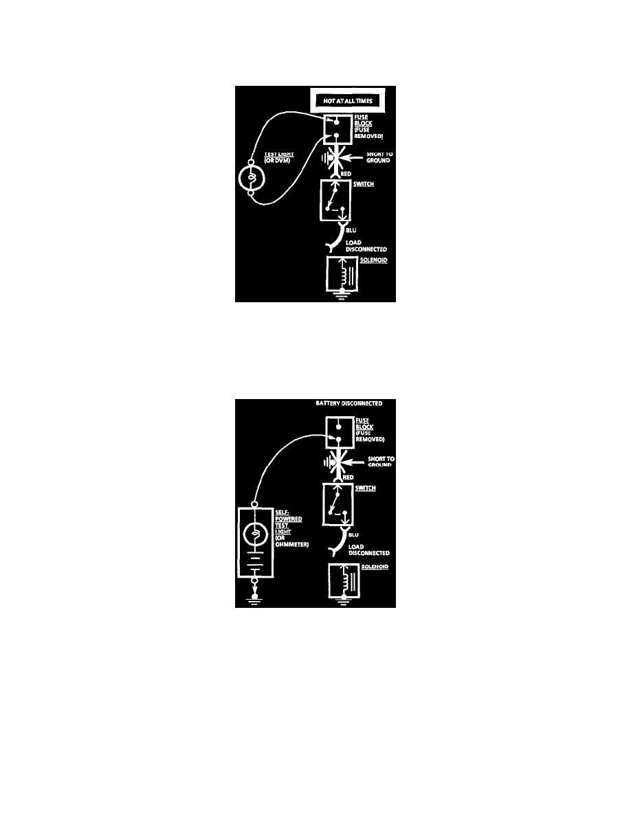
With A Test Light or Digital Multimeter (DMM)
1. Remove the blown fuse and disconnect the load.
2. Connect a test light or voltmeter across the fuse terminals (be sure that the fuse is powered).
3. Beginning near the Fuse Block, wiggle the harness from side to side. Continue this at convenient points (about 6 inches apart) while watching the
test light or DMM.
4. when the test light glows, or the DMM registers, there is a short to ground in the wiring near that point.
With A Self-Powered Test Light or Ohmmeter
1. Remove the blown fuse and disconnect the Battery and load.
2. Connect one lead of a self-powered test light or ohmmeter to the fuse terminal on the load side.
3. Connect the other lead to a known good ground.
4. Beginning near the Fuse Block, wiggle the harness from side to side. Continue this at convenient points (about 6 inches apart) while watching the
self-powered test light or ohmmeter.
5. When the self-powered test light glows, or the ohmmeter registers, there is a short to ground in the wiring near that point.
Fuses Powering Several Loads
1. Find the schematic in "Fuse Block Details," for the fuse that has blown.
2. Open the first connector or switch leading from the fuse to each load.
3. Replace the fuse.
^
If the fuse blows, the short is in the wiring leading to the first connector or switch. Use a test light or DMM.
^
If fuse does not blow, refer to next step.
4. Close each connector or switch until the fuse blows in order to find which circuit has the short. Connect test light or DMM at the connector to the
suspect circuit (disconnected) rather than at the fuse terminals.