Hombre XS Space Cab 2WD L4-2.2L CPC (1999)

Engine Control Module: Description and Operation
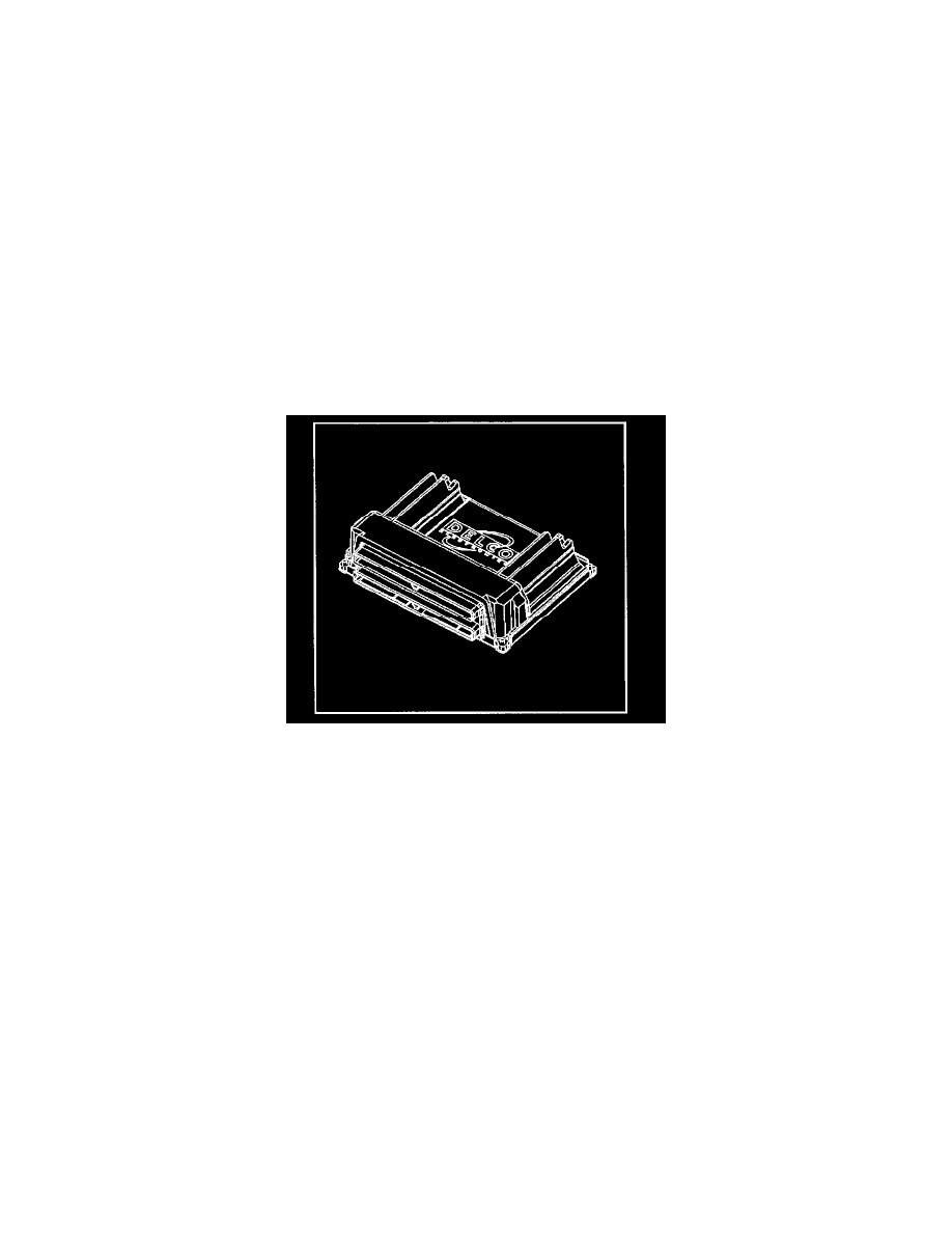
Powertrain Control Module
Powertrain Control Module (PCM)
Powertrain Control Module Description
The Control Module refers to the Powertrain Control Module (PCM) and the Vehicle Control Module (VCM). The control module is designed to
maintain exhaust emission levels to Federal or California standards while providing excellent driveability and fuel efficiency. Review the components
and wiring diagrams in order to determine which systems are controlled by each specific control module. The control module monitors numerous engine
and vehicle functions. The control module controls the following operations:
-
Fuel control
-
Ignition Control (IC)
-
Knock Sensor (KS) system
-
Automatic transmission shift functions
-
Cruise Control Enable
-
Generator
-
Evaporative Emission (EVAP) Purge
-
A/C Clutch Control
-
Cooling Fan Control
Powertrain Control Module
Powertrain Control Module (PCM)
The Powertrain Control Module (PCM) is the control center of the fuel injection system. It constantly looks at the information from various sensors, and
controls the systems that affect emission or engine performance. The PCM also performs the diagnostic function of the system. It can recognize
operational problems, alert the driver through the Malfunction Indicator Lamp (MIL), and store a DTC or DTCs which identify the problem areas to aid
the technician in making repairs. See Introduction in Powertrain Control Module for more information on using the diagnostic functions of the PCM.
PCM Function
Powertrain Control Module Function
The Control Module supplies a buffered voltage to various sensors and switches. The input and output devices in the control module include an analog to
digital converters, signal buffers, counters, and special drivers. The Control Module controls most components with electronic switches which complete
a ground circuit when turned ON. These switches are arranged in groups of 4 and 7 called one of the following:
-
Quad Driver Module
-
Output Driver Modules
The surface mounted Quad Driver Module can independently control up to 4 outputs (Control Module) terminals. The Output Driver Modules can
independently control up to 7 outputs. Not all outputs are always used.
PCM Voltage Description
PCM Voltage Description
