
Hombre XS Space Cab 2WD V6-4.3L (1998)
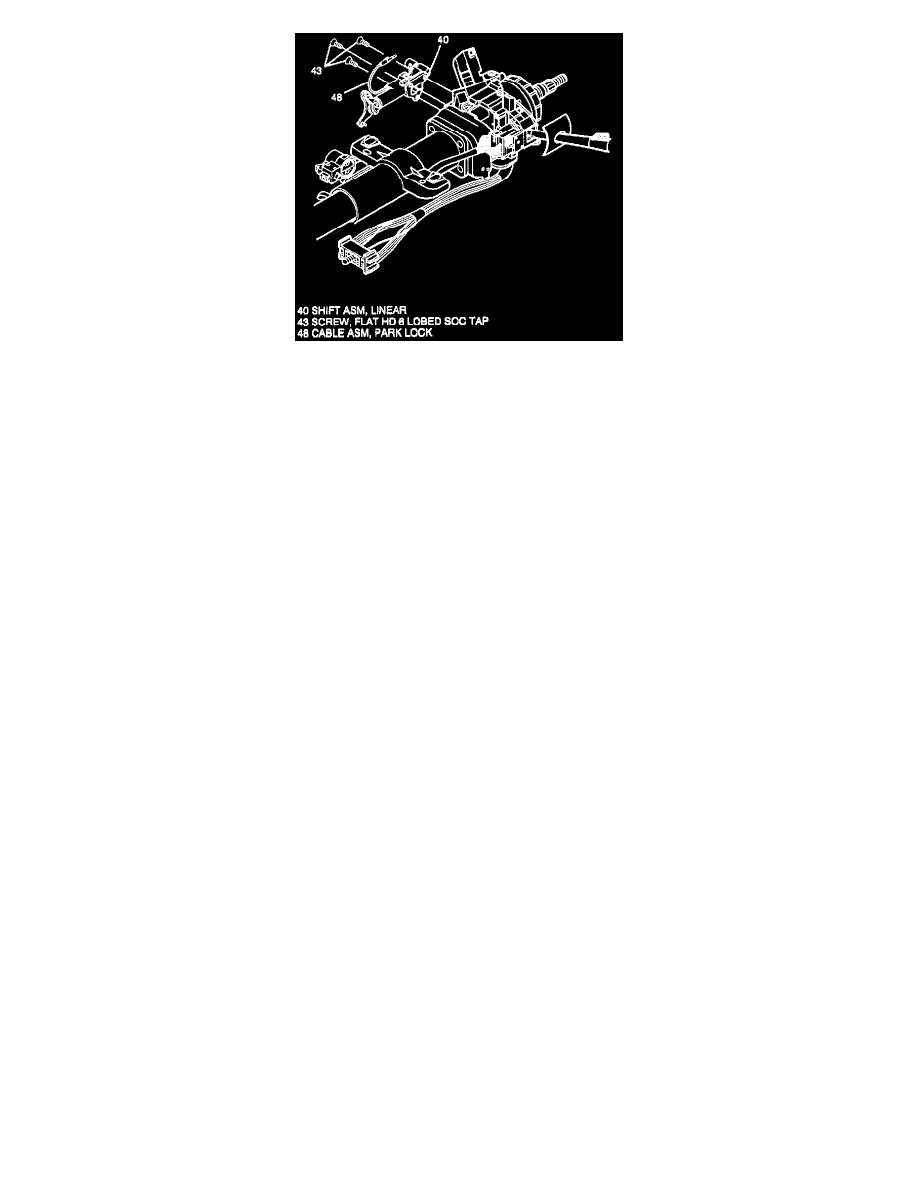
Removing Linear Shift Assembly
5. Three flat head 6-lobed socket tap screws (43).
-
Shift column to "NEUTRAL" position to gain access to lower socket tap screw (43).
6. Linear shift assembly (40) from column.
Install or Connect
NOTICE: Refer to the fastener NOTICE. See: Service Precautions Failure to do so may result in component damage or malfunction of steering column.
1. Linear shift assembly (40) to column.
2. Three flat head 6-lobed socket tap screws (43).
-
Linear shift assembly (40) must be out of "PARK" position to install lower socket tap screw (43). Tighten screws (43) to 10 N.m (89 lb.in.).
3. Transaxle cable to inner shift cable ball stud on cable shift cam assembly (44).
4. Park lock cable assembly (48) to lock module assembly (15).
-
Lock cylinder should be in "OFF-LOCK" position and gear shift in "PARK" position.
-
Locking tab on end of cable (48) to slot in module assembly (15).
5. Actuator arm of electrical (BTSI) actuator (61) to outer shift cable ball stud on cable shift cam assembly (44).
6. Do Adjust and Inspect, "Install or Connect", ELECTRICAL (BTSI) ACTUATOR, (Tilt Steering Column). See: Steering and
Suspension/Steering/Steering Column/Service and Repair
7. Do all steps "Install or Connect", LOWER SHROUD, UPPER SHROUD, (Tilt Steering Column). See: Steering and Suspension/Steering/Steering
Column/Service and Repair
LINEAR SHIFT ASSEMBLY (DISASSEMBLY)
BALL & ACTUATOR ASSEMBLY
SHIFT LEVER CLEVIS
PARK LOCK CABLE ASSEMBLY
G/S LEVER ASSEMBLY SUPPORT BRACKET
(c/s only)
Tools Required: J 41352 Modular Column Holding Fixture.