
Impulse L4-1994cc 2.0L (1985)
Engine Control Module: Component Tests and General Diagnostics
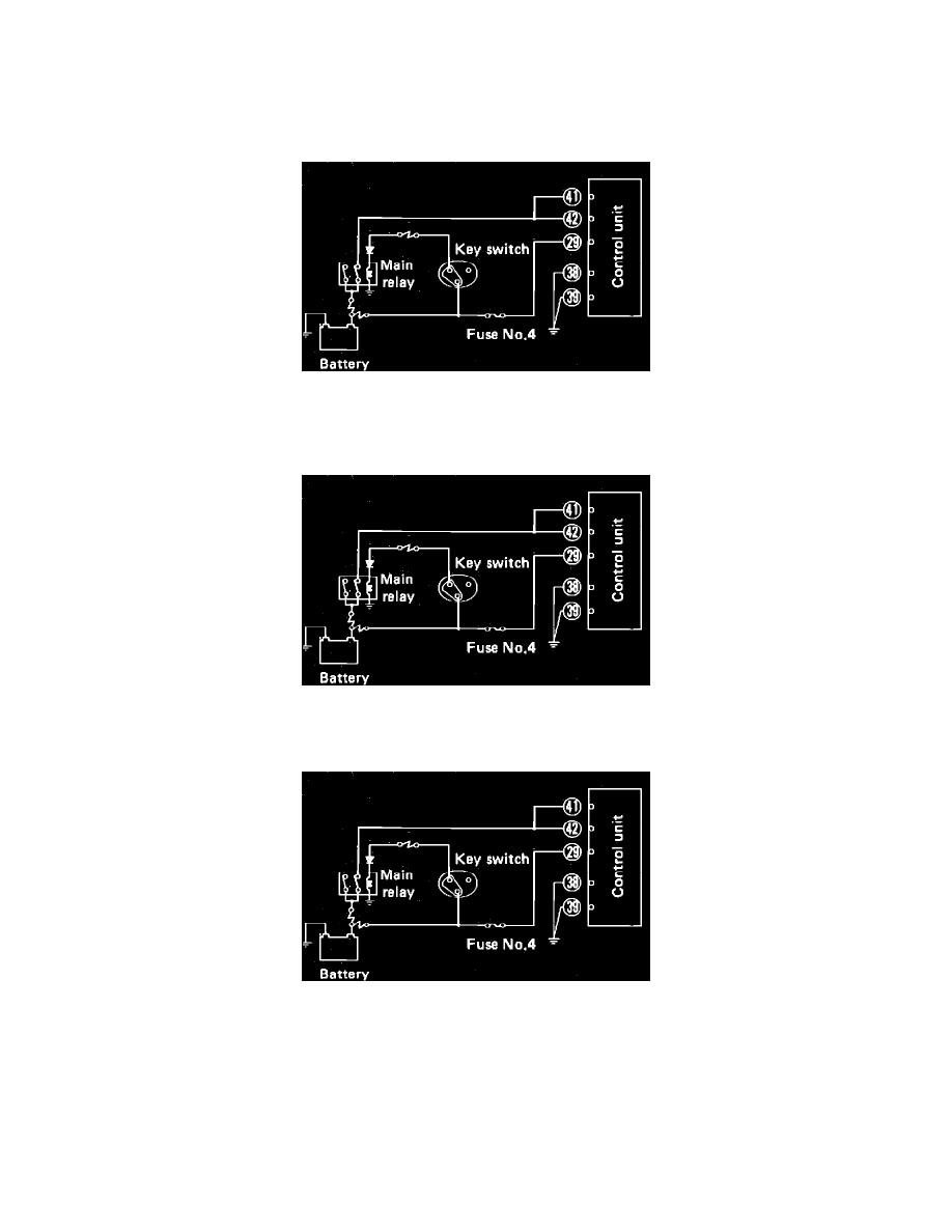
Control Unit Power Supply Test
1.
Disconnect control unit harness electrical connector, then turn ignition switch to the ON position.
Fig. 8 Checking control unit power supply.
2.
Check that voltage is present at connector terminals No. 29 and 41, Fig. 8. If voltage is not present, check main relay, starter switch, fuses, fusible
link wires and related circuits. Repair or replace parts as necessary.
Fig. 8 Checking control unit power supply.
3.
Check continuity between connector terminals No. 38, 39 and ground, Fig. 8. If continuity is not present, repair or replace ground cable.
Fig. 8 Checking control unit power supply.