
Rodeo LS 4WD V6-3.2L (1998)
should rest on the edge of the tappet without touching the shim.
10. Slowly turn the crankshaft (or camshaft) pulley counterclockwise so that when the valve closes, the tool catches between the camshaft and the
tappet, holding the valve slightly open.
NOTE:
Do not turn the crankshaft (or camshaft) pulley too far or in the wrong direction. If you do, you might break the tool, or worse yet, damage the
cylinder head.
11. Insert a pick or a small screwdriver into the tappet notch, and pry out the shim.
12. Wipe off the shim, then write its number on the Valve Inspection Chart for that valve and cylinder. If there is no number on the shim, measure its
thickness with a micrometer, and write down the measurement on the Valve Inspection Chart.
13. Follow the directions on the Valve Shim Replacement Chart to select the correct shim.
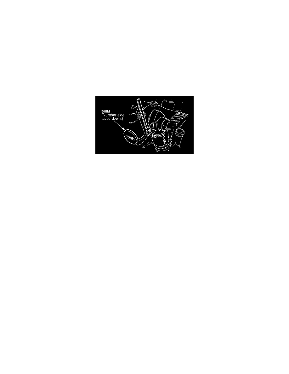
14. Insert the correct shim, number side down, into the tappet. Make sure the shim is fully seated.
15. Release and remove the tool by turning the crankshaft (or camshaft) pulley clockwise.
16. Turn the crankshaft (or camshaft) pulley clockwise until the cam lobe again points away from the valve.
17. Recheck the valve clearance using the Go/No-Go method (see step 4).
-
If the clearance is OK, repeat steps 6 thru 17 for the other valves needing adjustment.
-
If the clearance is still incorrect, repeat steps 6 through 17 until it is correct, then adjust the remaining valves.
18. Turn the camshaft pulleys until the single timing dot (right cylinder bank) and dual timing dots (left cylinder bank) align with the single timing
dots on the camshaft drive gears.
19. Install the cylinder head covers with new gaskets. Torque the cover bolts to 9 N.m (6.5 lb-ft).
Off-Vehicle Valve Adjustment
1. Make a copy of the Valve Inspection Chart.
2. Make a copy of the Valve Shim Replacement Chart, then tape the pages together, side-by-side.
3. Measure the valve clearances using the Go/No-Go method (see the note below). The clearances must be
-
Intake valves: 0.25 mm +0.05 mm
-
Exhaust valves: 0.30 mm +0.05 mm
NOTE:
-
To measure with the Go/No-Go method, use two feeler gauges, one to measure the smallest allowable clearance, and the other to measure
the largest.
-
If the small gauge fits and the large gauge doesn't, the valve adjustment is OK.
-
If the small gauge doesn't fit, or if the large gauge slides easily, the valve needs adjustment.