
Rodeo LS 4WD V6-3.2L (1998)
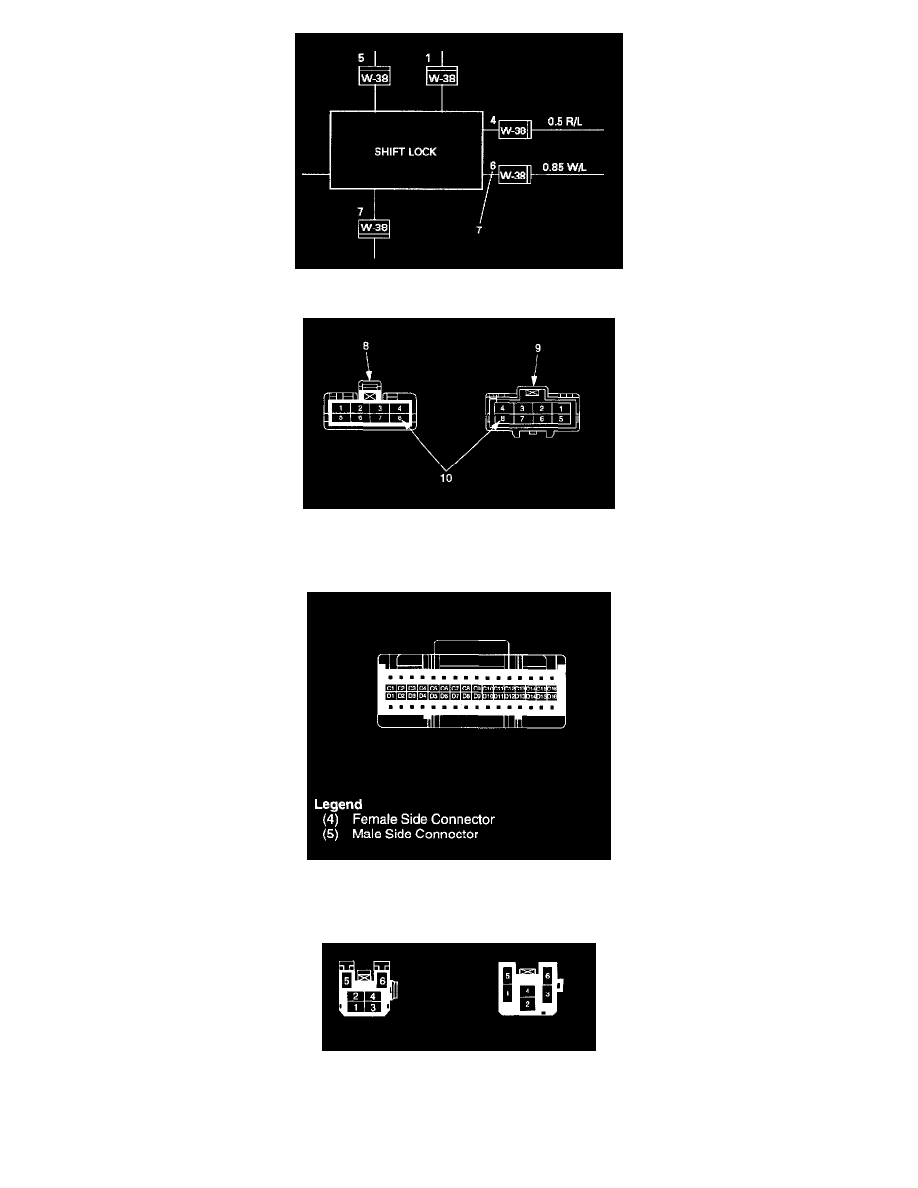
- The applicable terminal number (7) is shown for each connector.
- Connector terminal numbers (10) are clearly shown.
Make side connector (9) terminal numbers are in sequence from upper right to lower left.
Female side connector (8) terminal numbers are in sequence from upper left to lower right.
NOTE:
1. For those connectors on which specific terminal numbers or symbols are shown (such as PCM), the terminal numbers or symbols are used in the
circuit diagram, irrespective of the above rule. See figure.
2. The connectors used for relays have their own terminal number assignment, irrespective of the above rule. See figure.
Double Lock Type Connector