
Rodeo S 2WD L4-2.2L (1999)
-
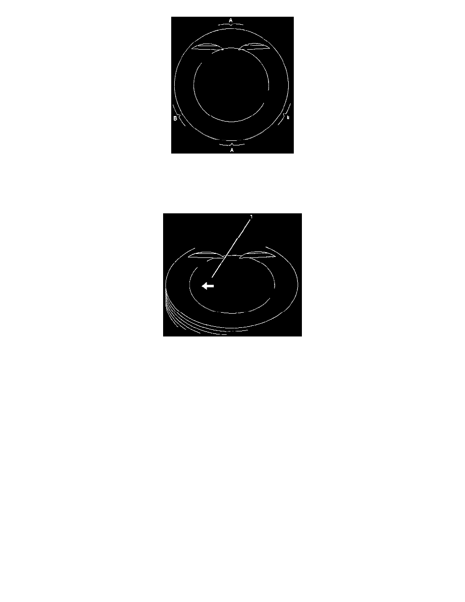
Piston rings position (A) every 180°.
Oil scraper rings (B)-offset 25 to 50 mm / 1 to 2 inch to left and right from gap of intermediate ring.
-
Insert the piston/connecting rod assemblies into each cylinder with the piston ring compressor. The front marks must be facing the front of the
engine.
-
Match the numbered caps with the numbers on the connecting rods. Align the punched marks on the connecting rods and caps.
-
Arrow (1) on piston head points to engine timing side, bead on connecting rod points to flywheel side.
-
Tighten the bolts in 3 steps:
1st step: 35 Nm (25 ft. lbs.)
2nd step: 45°
3rd step: 15°
5. Install the balance unit assembly and tighten the bolts in 2 steps:
1st step: 20 Nm (14 ft. lbs.)
2nd step: 45°
Refer to the Balance Unit Assembly section.
6. Install oil pump assembly (5), refer to Oil Pump.
7. Install oil strainer.
Torque: 8 Nm (5.8 ft. lbs.)
8. Install oil pan support and tighten the bolts to the specified torque.
Torque: 20 Nm (14 ft. lbs.)
9. Install oil pan.
1. Completely remove all residual sealant, lubricant and moisture from the sealing surfaces. The surfaces must be perfectly dry.
2. Apply a correct width bead of sealant (TB-1207C or its equivalent) to the contact surfaces of the oil pan. There must be no gaps in the bead.
3. The oil pan support must be installed within 5 minutes after sealant application.
4. Tighten the bolts in two steps.