
Rodeo S 2WD L4-2.2L (1999)
Balance Shaft: Adjustments
ADJUSTMENT
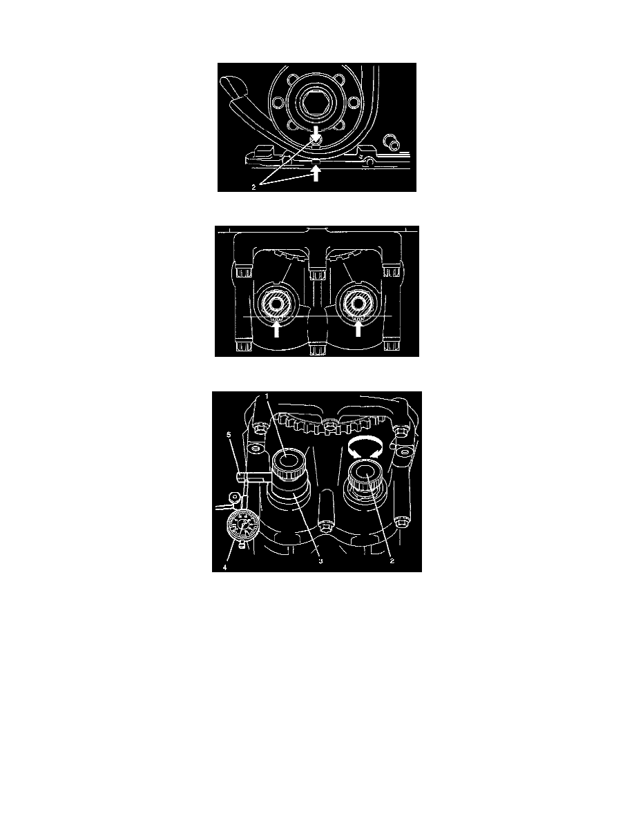
1. Turn crankshaft in engine rotational direction to alignment mark (2) 1st cylinder "TDC".
2. In this crankshaft position, the flattened side (arrows) of both balancer shafts must face downward and must be on a horizontal line.
3. Screw measuring device J-43038 (3) with long knurled bolt (1) into 1st balancer shaft (intake side) and tighter hard-tight measuring arm (5) must
point in "9 o'clock" direction shown in this illustration.
Install dial gauge holder with dial gauge (4) on cylinder block.