
Rodeo S 2WD L4-22L (1999) | Instrument Panel, Gauges and Warning Indicators | Clock
Female side connector (8) terminal numbers are in sequence from upper left to lower right.
NOTE:
1. For those connectors on which specific terminal numbers or symbols are shown (such as PCM), the terminal numbers or symbols are used in
the circuit diagram, irrespective of the above rule.
Refer to the figure.
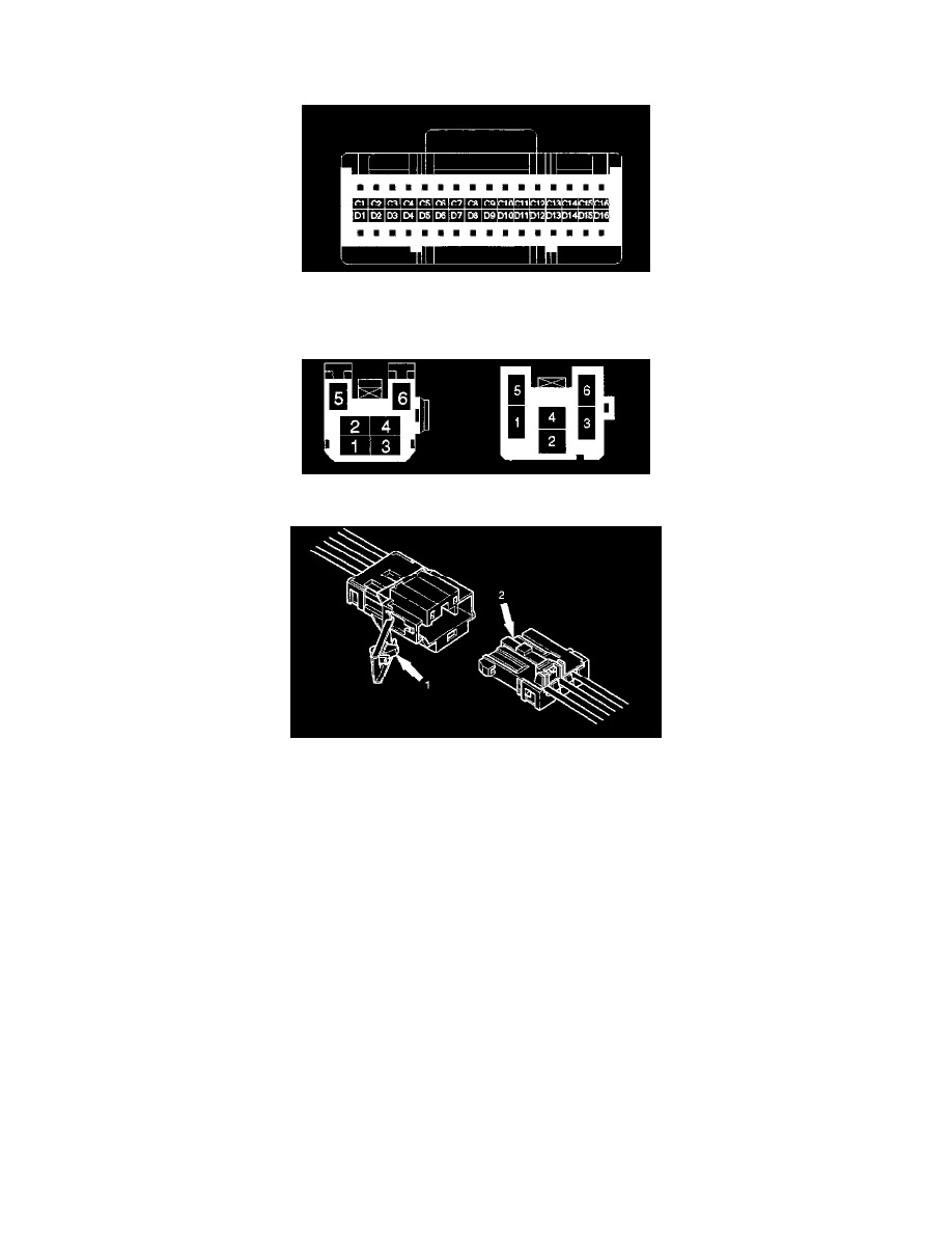
2. The connectors used for relays have their own terminal number assignment, irrespective of the above rule. Refer to the figure.
Double Lock Type Connector
Doublelock type yellow color connectors are used for supplemental restraint system-air bag circuit. When removing the cable harness, disconnect the
connector by unlocking at two places, outside (1) and inside (2). In such a case, do not pull the cables. Otherwise, cable disconnection may occur.
When connecting the connector, insert the connector completely and lock at outside. Imperfect locking may cause malfunction of SRS system circuit.
Reading the Circuit Diagram
In this, each system has its own parts location illustration and circuit diagram. And harness connector faces used in the circuit diagram are shown at the
end.