
Rodeo S 2WD L4-2.2L (1999)
Knock Sensor: Description and Operation
Knock Sensor System
Insufficient gasoline octane levels may cause detonation in some engines. Detonation is an uncontrolled explosion (burn) in the combustion chamber.
This uncontrolled explosion results from a flame front opposite that of the normal flame front produced by the spark plug. The rattling sound normally
associated with detonation is the result of two or more opposing pressures (flame fronts) colliding within the combustion chamber. Light detonation is
sometimes considered normal, but heavy detonation could result in engine damage.
A knock sensor system is used to control detonation. This system is designed to retard spark timing up to 20 degrees to reduce detonation in the engine.
This allows the engine to use maximum spark advance to improve driveability and fuel economy.
The knock sensor system has two major components:
-
The knock sensor (KS) module.
-
The knock sensor.
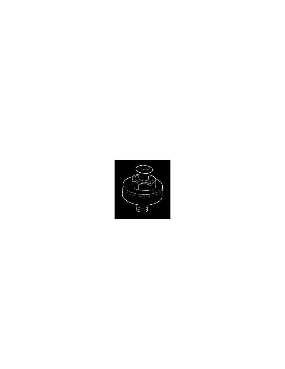
Knock Sensor
The knock sensor, mounted in the engine block near the cylinders, detects abnormal vibration in the engine. The sensor produces an AC output signal of
about 10 millivolts. The signal amplitude and frequency are dependent on the amount of knock being experienced. The signal voltage increases with the
severity of the knock. This signal voltage is input to the PCM. The PCM then retards the ignition control (IC) spark timing based on the KS signal being
received.
The PCM determines whether knock is occurring by comparing the signal level on the KS circuit with the voltage level on the noise channel. The noise
channel allows the PCM to reject any false knock signal by indicating the amount of normal engine mechanical noise present. Normal engine noise varies
depending on the engine speed and load. If the voltage level on the KS noise channel circuit is below the range considered normal, DTC P0327 will set,
indicating a fault in the KS circuit or the knock sensor. If the PCM determines that an abnormal minimum or maximum noise level is being experienced a
DTC will set.
Knock Sensor Module
The PCM contains a knock sensor (KS) module. The KS module contains the circuitry which allows the PCM to utilize the KS signal and diagnose the
KS sensor and the KS circuitry. If the KS module is missing or faulty, a continuous knock condition will be indicated, and the PCM will set a DTC.
Although it is a plug-in device, the KS module is not replaceable. If the KS module is faulty, the entire PCM must be replaced.