
Rodeo S 2WD L4-2.2L (1999)
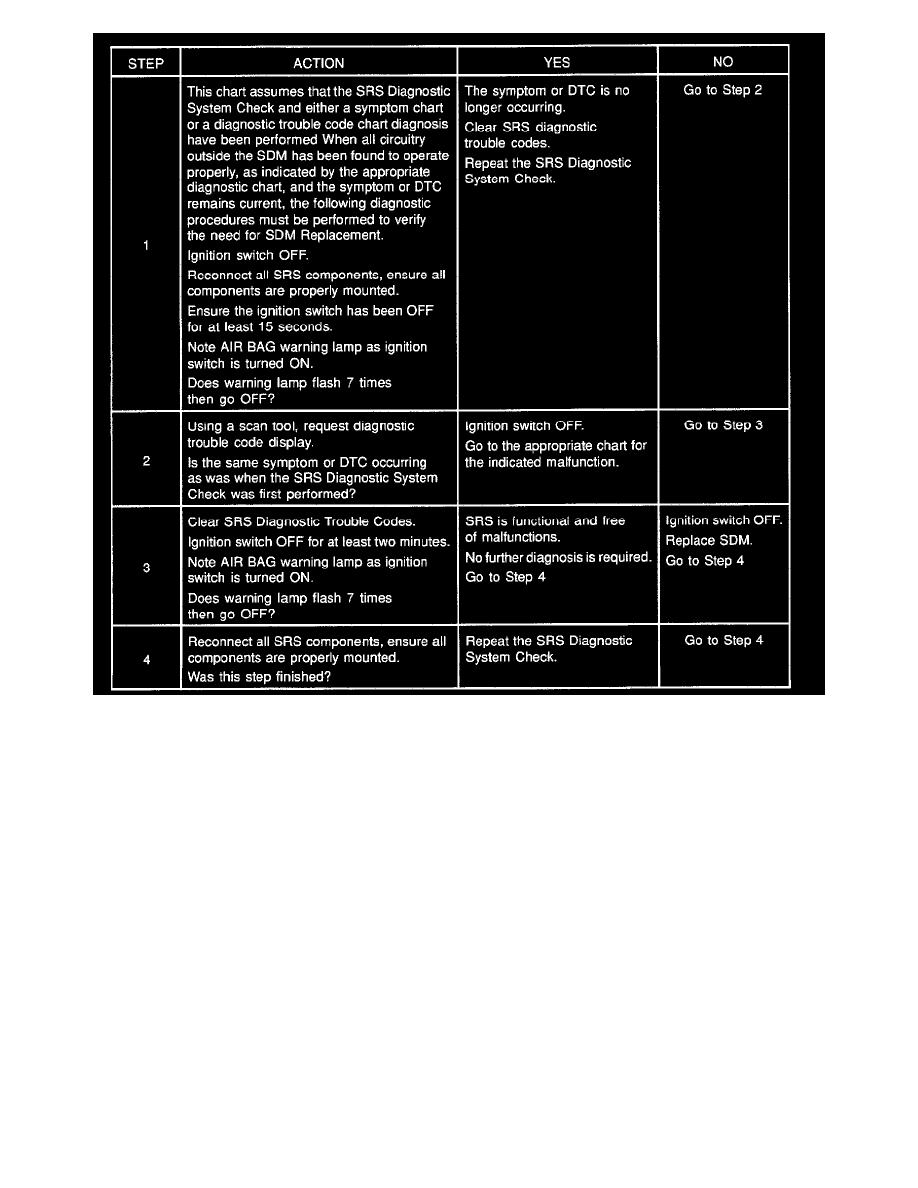
Chart Test Description:
Number(s) below refer to step number(s) on the diagnostic chart:
1. This test confirms a current malfunction. If no current malfunction is occurring (history DTC set) the Diagnostic Aids for the appropriate
diagnostic trouble code should be referenced. The SDM should not be replaced for a history diagnostic trouble code.
2. This test checks for a malfunction introduced into the SRS during the diagnostic process. It is extremely unlikely that a malfunctioning SDM
would cause a new malfunction to occur during the diagnostic process.
3. When all circuitry outside the SDM has been found to operate properly, as indicated by the appropriate diagnostic chart, then and only then should
the SDM be replaced.
WARNING: DURING SERVICE PROCEDURES. BE VERY CAREFUL WHEN HANDLING A SENSING AND DIAGNOSTIC MODULE
(SDM). NEVER STRIKE OR JAR THE SDM. NEVER POWER UP THE SRS WHEN THE SDM IS NOT RIGIDLY ATTACHED TO THE
VEHICLE. ALL SDM AND MOUNTING BRACKET FASTENERS MUST BE CAREFULLY TORQUED AND THE ARROW MUST BE
POINTING TOWARD THE FRONT OF THE VEHICLE TO ENSURE PROPER OPERATION OF THE SRS. THE SDM COULD BE
ACTIVATED WHEN POWERED WHILE NOT RIGIDLY ATTACHED TO THE VEHICLE WHICH COULD CAUSE DEPLOYMENT
AND RESULT IN PERSONAL INJURY.