
Rodeo S 2WD L4-2.2L (1999)
Generator: Testing and Inspection
Inspection Procedure
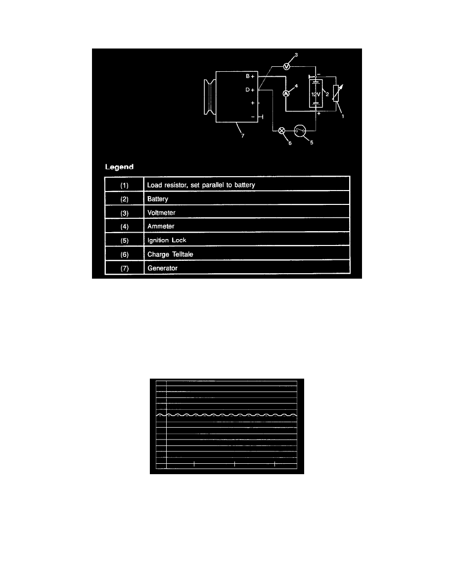
Generator Power and Circuit Diagram
1. Disconnect battery.
2. Close off connecting cable from alternator terminal B+.
3. Set ammeter (measuring range 100 A) in disconnected line.
4. Connect controllable load resistor to battery terminal.
5. Set resistor in front of connection to 0; connect first to battery, then to resistor.
6. Connect tachometer.
7. Connect oscilloscope according to manufacturer's instructions.
8. Connect battery.
9. Start engine and read off resulting current at various engine speeds.
Generator Power
1. Adjust load resistor, if the required load currents are not attained.
2. The shape of the voltage curves on oscilloscope curve should be regular.
3. Test value: 5 to 7 A.
4. If the required minimum current intensity is not attained, or if the oscilloscope picture shows variations, the alternator should be overhauled.