
Trooper LS V6-3.5L (1998)
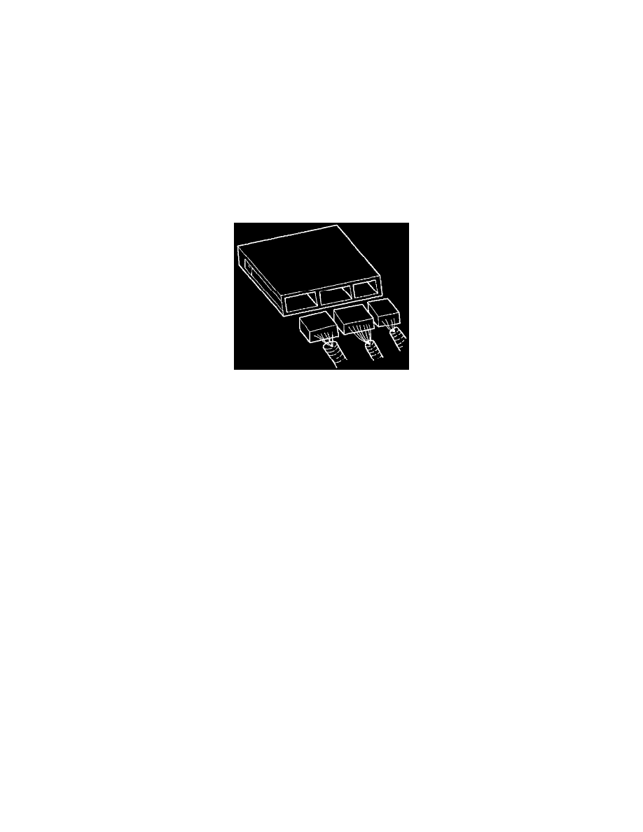
Engine Control Module: Description and Operation
Component Description
General Description
The powertrain control module (PCM) is located in the passenger compartment below the center console. The PCM controls the following:
-
Fuel metering system.
-
Transmission shifting (automatic transmission only).
-
Ignition timing.
-
On-board diagnostics for powertrain functions.
The PCM constantly observes the information from various sensors. The PCM controls the systems that affect vehicle performance. The PCM
performs the diagnostic function of the system. It can recognize operational problems, alert the driver through the MIL (Service Engine Soon lamp)
and store diagnostic trouble codes (DTCs). DTCs identify the problem areas to aid the technician in making repairs.
This engine uses 2 different control modules:
-
IPCM-6kT for automatic transmission-equipped vehicles.
-
ISFI-6 for manual transmission-equipped vehicles.
PCM Function
The PCM supplies either 5 or 12 volts to power various sensors or switches. The power is supplied through resistances in the PCM which are so high
in value that a test light will not light when connected to the circuit. In some cases, even an ordinary shop voltmeter will not give an accurate reading
because its resistance is too low. Therefore, a digital voltmeter with at least 10 megohms input impedance is required to ensure accurate voltage
readings. Tool J 39200 meets this requirement. The PCM controls output circuits such as the injectors, IAC, cooling fan relays, etc., by controlling the
ground or the power feed circuit through transistors or through either of the following two devices:
-
Output Driver Module (ODM)
-
Quad Driver Module (QDM)
PCM Components
The PCM is designed to maintain exhaust emission levels to government mandated standards while providing excellent driveability and fuel
efficiency. The PCM monitors numerous engine and vehicle functions via electronic sensors such as the throttle position (TP) sensor, heated oxygen
sensor (HO2S) and vehicle speed sensor (VSS). The PCM also controls certain engine operations through the following:
-
Fuel injector control
-
Ignition control module
-
Knock sensor
-
Automatic transmission shift functions
-
Cruise control
-
Evaporative emission (EVAP) purge
-
A/C clutch control
PCM Voltage Description
The PCM supplies a buffered voltage to various switches and sensors. It can do this because resistance in the PCM is so high in value that a test light
may not illuminate when connected to the circuit. An ordinary shop voltmeter may not give an accurate reading because the voltmeter input impedance
is too low. Use a 10-megohm input impedance digital voltmeter (such as J 39200) to assure accurate voltage readings.
The input/output devices in the PCM include analog-to-digital converters, signal buffers, counters, and special drivers. The PCM controls most
components with electronic switches which complete a ground circuit when turned "ON." These switches are arranged in groups of 4 and 7, called
either a surface-mounted quad driver module (QDM), which can independently control up to 4 output terminals, or QDMs which can independently
control up to 7 outputs. Not all outputs are always used.
PCM Input/Outputs
Inputs - Operating Conditions Read
-
Air Conditioning ON" or "OFF"