
Trooper LS V6-3.5L (1998)
Malfunction Indicator Lamp: Testing and Inspection
Diagnostic Chart
No Malfunction Indicator Lamp (MIL)
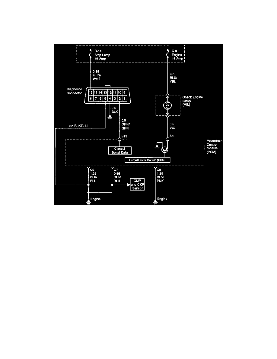
Circuit Description
The "Check Engine" lamp (MIL) should always be illuminated and steady with the ignition "ON" and the engine stopped. Ignition feed voltage is
supplied to the MIL bulb through the meter fuse. The powertrain control module (PCM) turns the MIL "ON" by grounding the MIL driver circuit.
Diagnostic Aids
An intermittent MIL may be cased by a poor connection, rubbed-through wire insulation, or a wire broken inside the insulation. Check for the
following items:
-
Inspect the PCM harness and connections for improper mating, broken locks, improperly formed or damaged terminals, poor terminal-to-wire
connection, and damaged harness.
-
If the engine runs OK, check for a faulty light bulb, an open in the MIL driver circuit, or an open in the instrument cluster ignition feed.
-
If the engine cranks but will not run, check for an open PCM ignition or battery feed, or a poor PCM to engine ground.
Test Description
Number(s) below refer to the step number(s) on the Diagnostic Chart.
2. A "No MIL" condition accompanied by a no-start condition suggests a faulty PCM ignition feed or battery feed circuit.
9. Using a test light connected to B+, probe each of the PCM ground terminals to ensure that a good ground is present. Refer to PCM Terminal End
View for terminal locations of the PCM ground circuits.
12. In this step, temporarily substitute a known good relay for the PCM relay. The horn relay is nearby, and it can be verified as "good" simply by
honking the horn. Replace the horn relay after completing this step.
17. This vehicle is equipped with a PCM which utilizes an electrically erasable programmable read only memory (EEPROM). When the PCM is
replaced the new PCM must be programmed. Refer to P6M Replacement and Programming Procedures in Powertrain Control Module (PCM) and
Sensors.