
Trooper LS V6-3.5L (1998)
23. Holding the pinion shaft, push pinion toward the center bracket and turn the pinion clockwise or counterclockwise by one tooth of spline, then pull
OFF the pinion.
24. Remove thrust washer (24).
25. Remove center bracket
26. Remove pinion shaft.
REASSEMBLY
To install, follow the removal steps in the reverse order, noting the following points:
Grease application places
^
Bushing in rear cover and center bracket
^
Gears in reduction gear
^
Shift lever operating portion
^
Sliding portion to pinion
^
Plunger sliding portion of magnetic switch
Reassembling Yoke Assembly
Before reassembly, make sure that no metallic parts attach to the yoke assembly. Because of strong magnetic force, hold the yoke assembly and insert it
slowly into the armature.
Torque
Torque for each part (See Torque Specifications in this section)
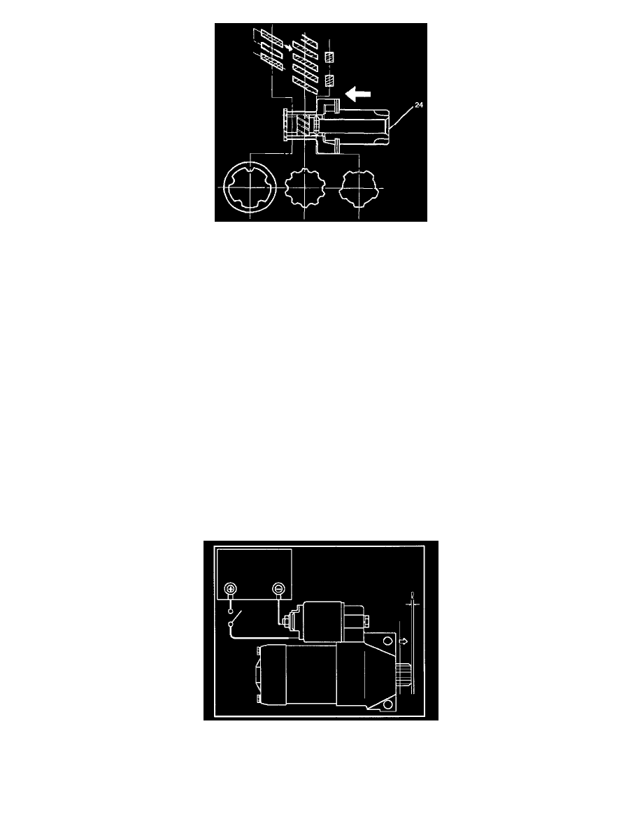
Pinion Jump-out Dimension
Connect the "+" cable of battery to terminal S and the "-" cable to terminal M. Turn the switch on, and measure pinion travel dimension in thrust
direction from the jump-out position.
In measuring the dimension, pull the pinion out a little in the arrow direction.
Dimension (L): 0.05 mm to 1.5 mm (0.002 in to 0.06 in)