
Trooper LS V6-3.5L (1998)
Circuit schematics break the entire electrical system into individual circuits. Electrical components that work together are shown together.
Each drawing is arranged so that current flows from positive, at the top, to ground, at the bottom. The "hot" labels at the top of a fuse show when the
ignition switch supplies power to that fuse.
Wires that connect to another circuit are shown with an arrowhead pointing in the direction of current flow. The name of the circuit that shares the wiring
is provided for reference.
"See Fuse Box Details" means there are more connections to other circuits that are not shown. All such shared circuits are shown on the Fuse Box
Details circuit schematic. "See Ground Distribution" means there are more shared ground circuits which are shown on the Ground Distribution
schematic.
No attempt is made on the schematic to represent components and wiring as they physically appear on the car. For example, a 4-foot length of wire is
treated no differently in a schematic from one which is only a few inches long. The number of cavities for each connector is listed in the Component
Location Index rather than illustrated. Similarly, switches and other components are shown as simply as possible, with regard to function only.
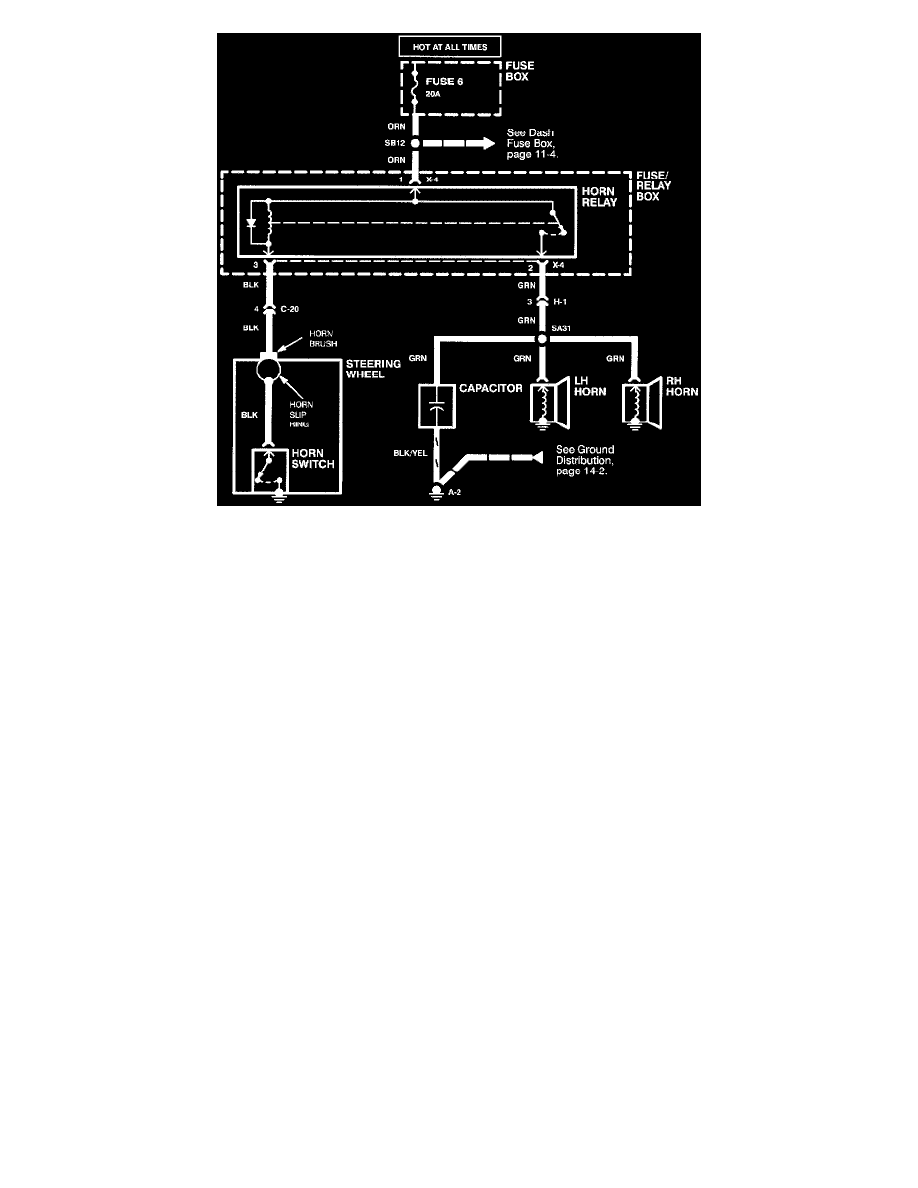
The example shows a Horns schematic. Locate the Horn schematic using the Circuit Index. The circuit schematic will look somewhat like the one to the
right. The schematic is read from top to bottom.
Voltage is applied to the Horn Relay at all times. When the relay coil is grounded by closing the Horn Switch, the relay contacts close. When the relay
contacts are closed, both the LH and RH Horns are energized.
Ground Distribution