
Trooper LS V6-3.5L (1998)
Valve Body: Service and Repair
Main Case
REMOVAL
1. Raise the vehicle and support it on jack stands.
2. Disconnect battery ground cable.
3. Remove transfer protector.
4. Drain fluid.
5. Support transfer case with a jack and remove third crossmember.
6. Remove sixteen 10 mm screws, main case oil pan, magnet and gasket.
7. Remove three 13 mm oil filter fixing screws, then remove oil filter.
8. Remove two 13 mm manual detent fixing screws, then remove roller and spring assembly.
9. Disconnect wiring harness from band control solenoid and shift solenoids. Pull only on connectors, not on wiring harness.
10. Remove four 13 mm servo cover fixing screws, then remove servo cover and gasket.
11. Remove seven 13 mm valve body fixing screws.
-
Disconnect the ground wire from the main case valve body.
12. Remove main case valve body with manual valve link and transfer plate. Note the position of the link (long end into valve, short end into range
selector lever).
13. Remove transfer plate gasket from main case.
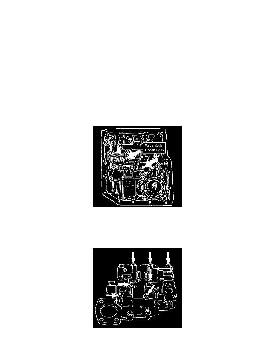
14. Remove two check balls from main case.
INSTALLATION
1. Install two check balls to main case.
2. Inspect electrical 4-pin connector and seal of main case. Replace if necessary.
3. Use two J-25025-B guide pin to install main case.
-
Install valve body assembly and manual valve link.
NOTE: Valve must be extended as the short end of manual valve link is connected to the range selector lever. Long end of link goes into valve.
4. Install seven 13 mm screws, and tighten them to the specified torque.