
Trooper S 2WD V6-3.5L (2001)
12.
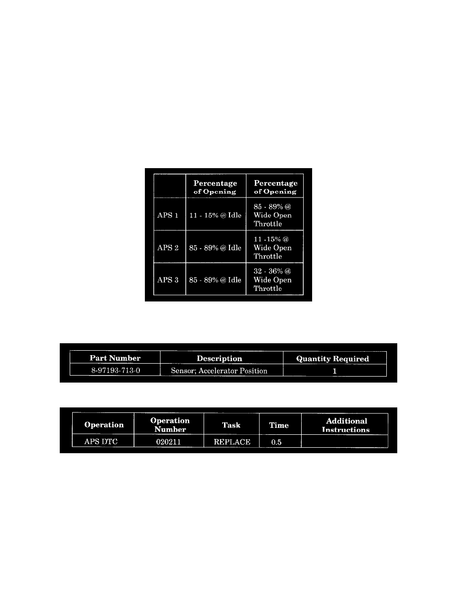
Adjust the Accelerator Position Sensor (APS) until the percentage of AP1 opening is between 11% and 15%. Tighten the Accelerator Position
Sensor screws (Figure 2)
13.
Using a DVOM, measure AP1 signal voltage at pin # 5 (white wire) of the APS connector. The set voltage, after the percentage is set, will be 0.6
volts at pin # 5 of the C-48.
NOTE:
Remember the Tech 2 does not give a voltage value For AP1. Please refer to 2000 Rodeo/Amigo, and/or 2000 Trooper Electrical Troubleshooting
Manual for circuit schematic.
14.
If less than 0.6 volt, troubleshoot for high resistance in the black wire (APS pin # 10) between the APS and PCM, or low reference voltage (should
be 5.0 v) from the PCM. Try a known good PCM first.
^
If equal to 0.6 volt, the circuit is functioning properly.
^
If more than 0.6 volt, troubleshoot for high resistance in the red wire (APS pin # 4) between the APS and PCM.
^
After the adjustment is performed please verify the reading shown.
15.
Remove the Tech 2 and return the vehicle to the customer.
PARTS INFORMATION
Use the new labor operation shown.
Labor Time includes administrative time allowance.