
VehiCROSS 4WD V6-3.5L (1999)
Steps 1 - 7
Test Description
IMPORTANT: Be sure to use the same diagnostic test equipment for all measurements.
The number(s) below refer to the step number(s) on the Diagnostic Chart.
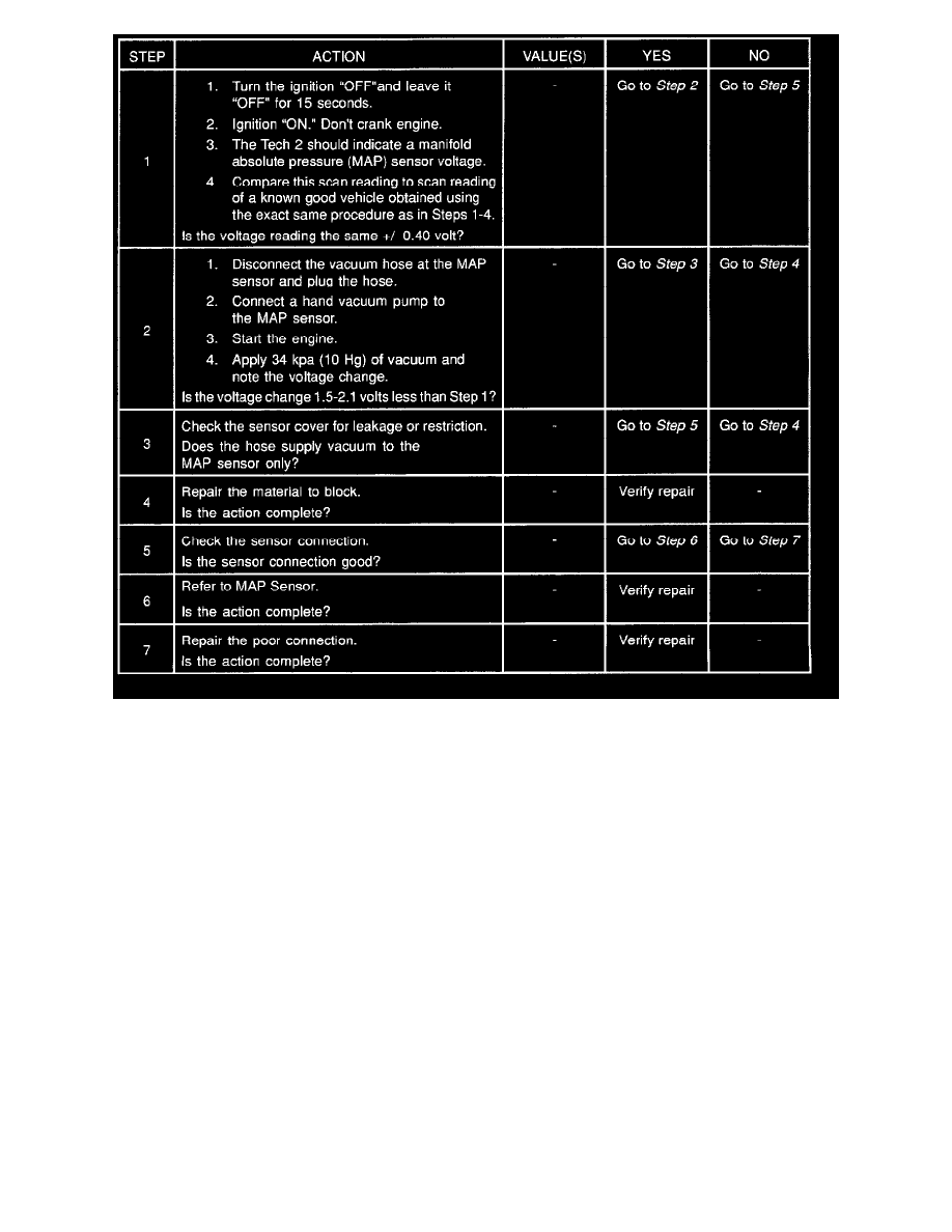
2. Applying 34 kpa (10 Hg) vacuum to the MAP sensor should cause the voltage to be 1.5 - 2.1 Volts less than the voltage at step 1. Upon applying
vacuum to the sensor, the change in voltage should be instantaneous. A slow voltage change indicates a faulty sensor.
3. Check the vacuum hose to the sensor for leaking or restriction. Be sure that no other vacuum devices are connected to the MAP hose.
IMPORTANT: Make sure the electrical connector remains securely fastened.
4. Disconnect the sensor from the bracket. Twist the sensor with your hand to check for an intermittent connection. Output changes greater than 0.10
volt indicate a bad sensor.