
VehiCROSS 4WD V6-3.5L (1999)
4. Install seven 13 mm screws, and tighten them to the specified torque.
Torque: 20 Nm (15 ft. lbs.)
5. Install 8.5 mm connector of ground wire the head of this valve body bolt and reinstall it. Tighten the bolt to the specified torque.
Torque: 20 Nm (15 ft. lbs.)
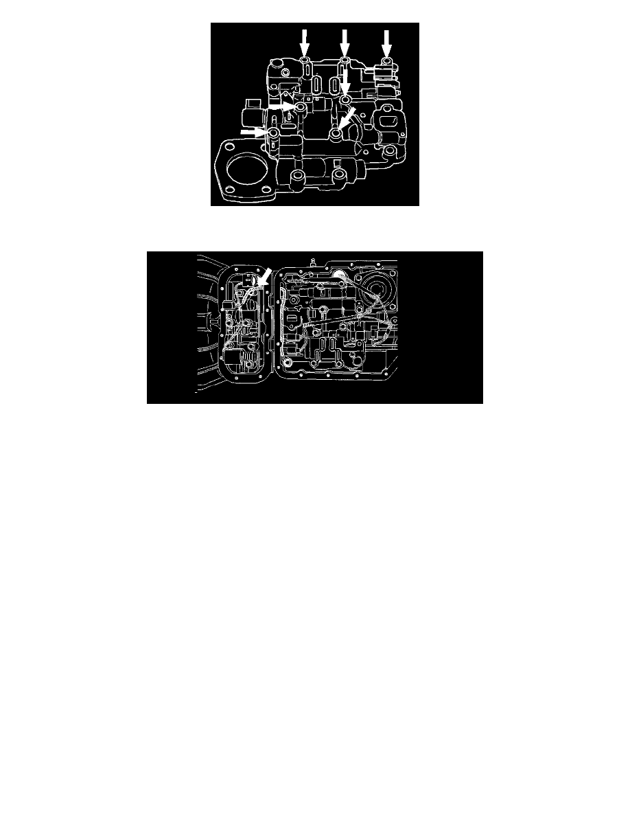
6. Remove two guide pins from main case.
7. Install servo cover gasket, cover, and four 13 mm screws. Tighten the screws to the specified torque.
Torque: 25 Nm (18 ft. lbs.)
8. Connect wiring harness to band control and shift solenoids.
9. Install roller and spring assembly to manual detent.
Install two 13 mm screws, and tighten them to the specified torque.
Torque: 20 Nm (15 ft. lbs.)
10. Install oil filter and three 13 mm screws. Tighten the screws to the specified torque.
Torque: 20 Nm (15 ft. lbs.)
11. Install oil pan gasket, magnet, oil pan and sixteen 10 mm screws. Tighten the screws to the specified torque.
Torque: 11 Nm (96 inch lbs.)
12. Install third crossmember and rear mount. Tighten the bolts and nuts to the specified torque.
Torque
Third crossmember bolt: 50 Nm (37 ft. lbs.)
Rear mount nut: 50 Nm (37 ft. lbs.)
13. Fill transmission through overfill screw hole of oil pan, using ATF DEXRON(R) III. Refer to Automatic Transmission Fluid; Service and Repair.
14. Connect battery ground cable.