
Engine
- Make
- Jaguar
- Model
- XJ-8 XJ Sedan (X308) Factory Service Manual
- Year
- 1998
- Section
- 303-01 Engine › Diagnosis and testing › Engine
Engine
Special tools
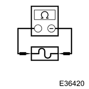 Digital multimeter
 Generic scan tool
Symptom Chart
Symptom Chart
| Condition | Possible source | Action |
|---|---|---|
| DTC P1392 VVT solenoid A circuit low input |
| GO to Pinpoint Test A |
| DTC P1397 VVT solenoid B circuit low input |
| GO to Pinpoint Test A |
| DTC P1393 VVT solenoid A circuit high input |
| GO to Pinpoint Test B |
| DTC P1398 VVT solenoid B circuit high input |
| GO to Pinpoint Test B |
| DTC P1396 VVT solenoid B malfunction |
| GO to Pinpoint Test C |
Pinpoint test A: P1392 (P1397) VVT solenoid circuit low input
P1392 (P1397) VVT solenoid circuit low input
NOTE: References in brackets are for Bank B (2)
Retrieve DTCS
NOTE: Battery and or ECM disconnection prior to scanning will erase all data, ensure that the correct DTC is present.
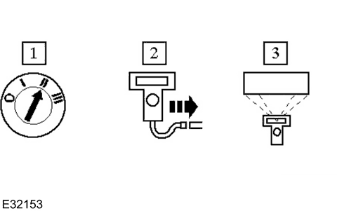
- Connect the scan tool
Have the DTC(s) and freeze frame data been recorded?
Yes → GO to A2.
Check fuse / relay
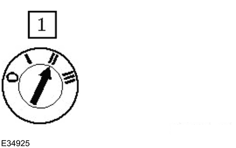
- Check that fuse F12 is good and that EMS control relay is energized
OK?
Yes → GO to A3.
No → Rectify as required
Check vvt coil resistance
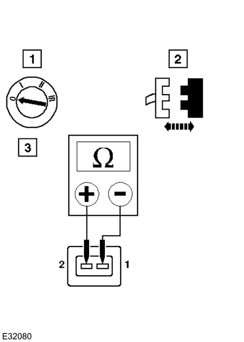
- With VVT connector PI031 - A bank or (PI032 - B bank) disconnected, measure the resistance between the pins 1 and 2 at the VVT actuator
Is the resistance less than 5 OHM or greater than 20 OHM?
Yes → Renew the VVT solenoid and test the system for normal operation.
No → GO to A4.
Check harness continuity
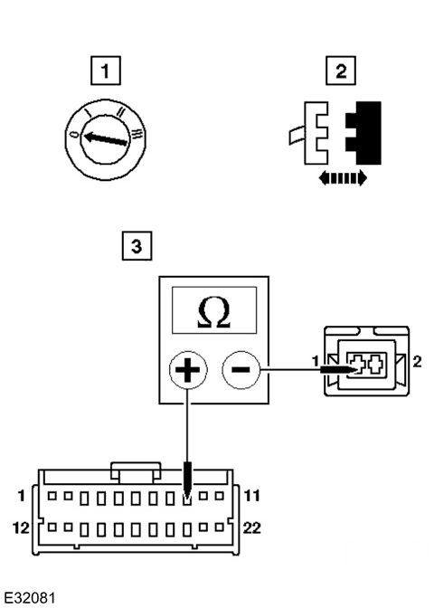
- With EM015 and PI031 (PI032) disconnected, measure the resistance between EM015/009 (EM015/008) and PI031/001 (PI032/001)
Is the resistance < 0.5 OHM?
Yes → GO to A5.
No → Inspect harness / connectors EM015, PI031 (PI032), PI001/016 (PI001/027) for corrosion, damage, bent or pushed back pins and repair as required. Test the system for normal operation.
Check harness (ground) continuity
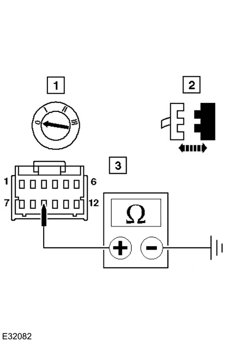
- With EM014 disconnected, measure the resistance between EM014/009 and ground EM016L
Is the resistance < 0.5 OHM?
Yes → Reconnect EM014, EM015, PI031 or (PI032) GO to A6.
No → Inspect harness / connector EM014, ground stud and splice EMS37 for corrosion, damage, bent or pushed back pins and repair as required. Test the system for normal operation.
END
- Perform appropriate service drive cycle and check for the presence of DTC.
Has the fault code cleared?
Yes → STOP
No → Contact Jaguar Service
Pinpoint test B: P1393 (P1398) VVT solenoid circuit high input
P1393 (P1398) VVT solenoid circuit high input
NOTE: References in brackets are for Bank B (2)
Retrieve DTCS
NOTE: Battery and or ECM disconnection prior to scanning will erase all data, ensure that the correct DTC is present.
- Connect the scan tool
Have the DTC(s) and freeze frame data been recorded?
Yes → GO to B2.
Check vvt coil continuity
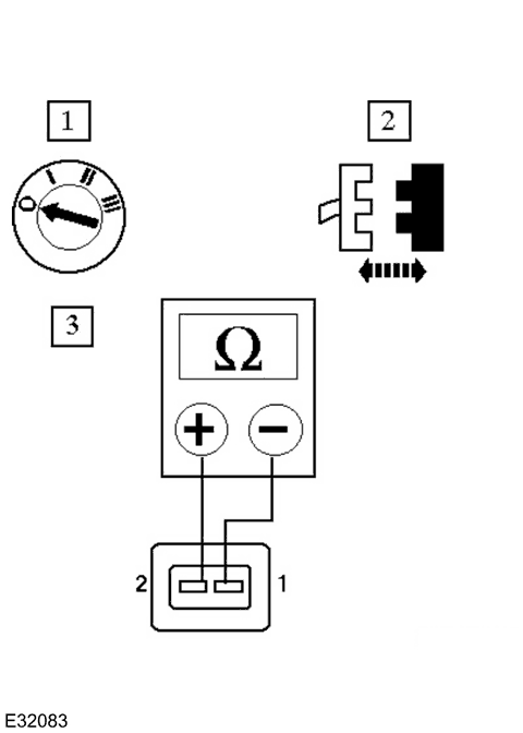
- With VVT connector PI031 - A bank or (PI032 - B bank) disconnected, measure the resistance between the pins 1 and 2 at the VVT actuator
Is the resistance >20 OHM?
Yes → Renew the VVT solenoid and test the system for normal operation.
No → GO to B3.
Check short to b+
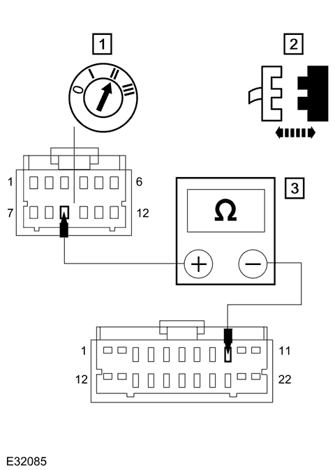
- Remove fuse F12
- With EM015, EM014, PI031 or (PI032) disconnected, measure the voltage between EM015/009 (EM015/008) and EM014/009
0 V?
Yes → Reconnect EM015 and EM014 and replace fuse F12 GO to B4.
No → Inspect EM015, PI031 or (PI032) for bent / pushed back pins or locate and repair the harness / connector PI001/016 or (PI001/027) Test the system for normal operation.
Check b+ at vvt solenoid
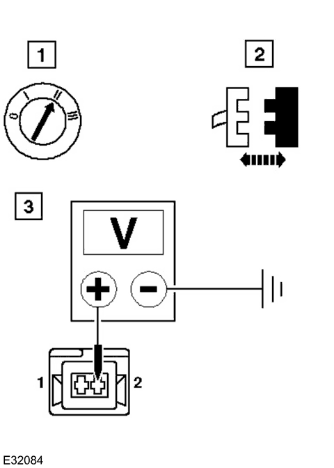
- Measure the voltage between PI031/002 (PI032/002) and ground EM016L
B+ ?
Yes → GO to B5.
No → Inspect EM020/010, PI001, PI031 (PI032) for bent / pushed back pins or locate and repair harness / splice PIS06.
Check harness short to ground
- With EM015 and EM014 disconnected, measure the insulation resistance between EM015/009 (EM015/008) and ground EM014/009
Is the resistance > 10 MOHM?
Yes → Do not reconnect GO to B6.
No → Inspect EM015, and EM014 for corrosion, bent / pushed back pins or locate and repair the harness / connector. Test the system for normal operation.
Check harness short core to core
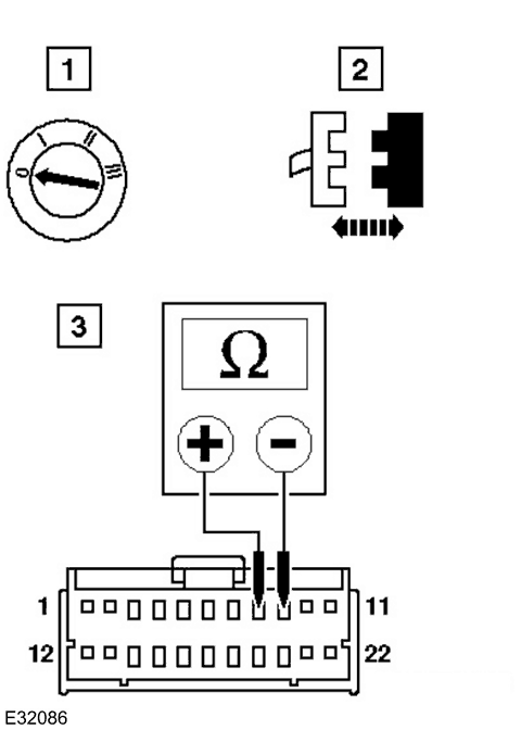
- With EM015, EM014 PI031 and PI032 disconnected, measure the insulation resistance between EM015/009 and EM015/008
Is the resistance > 10 MOHM?
Yes → Reconnect all connectors GO to B7.
No → Inspect EM015 and PI031 (PI032) for corrosion, bent / pushed back pins or locate and repair the harness / connector PI001/016 (PI001/027). Test the system for normal operation.
END
- Perform appropriate service drive cycle and check for the presence of DTC
Has the fault code cleared?
Yes → STOP
No → Contact Jaguar Service
Pinpoint test C: P1396 VVT solenoid malfunction
P1396 VVT solenoid malfunction
Retrieve DTCS
NOTE: Battery and or ECM disconnection prior to scanning will erase all data, ensure that the correct DTC is present.
- Connect the scan tool
Have the DTC(s) and freeze frame data been recorded?
Yes → GO to C2.
Check vvt coil continuity
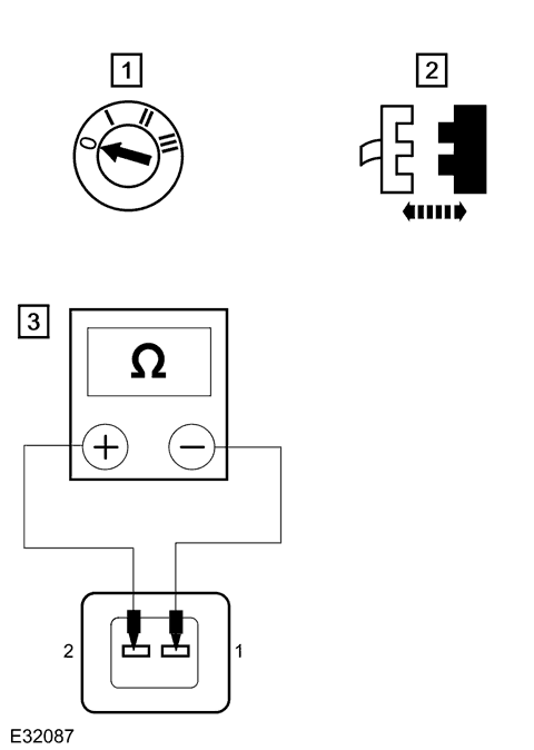
- With VVT connector PI032 disconnected, measure the resistance between the pins 1 and 2 at the VVT actuator
Is the resistance >20 OHM?
Yes → Renew the VVT solenoid and test the system for normal operation.
No → GO to C3.
Check short to b+
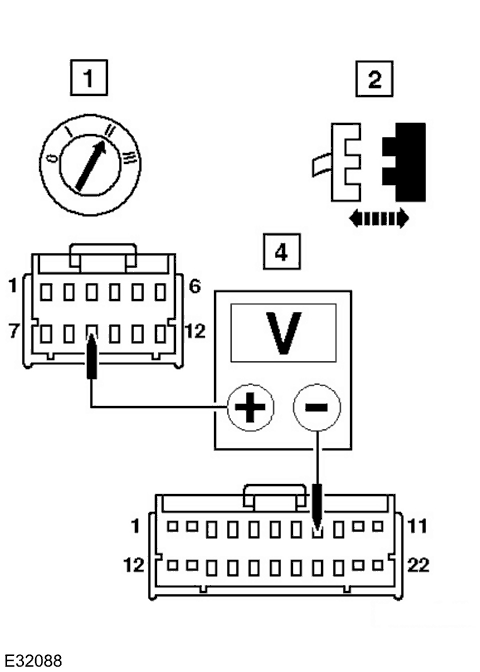
- Remove fuse F12
- With EM015, EM014, PI031 and PI032 disconnected, measure the voltage between EM015/008 and EM014/009
0 V?
Yes → Reconnect EM015 and EM014 and replace fuse F12 GO to C4.
No → Inspect EM015, PI001 or PI032 for bent / pushed back pins or locate and repair the harness / connector. Test the system for normal operation.
Check b+ at vvt solenoid
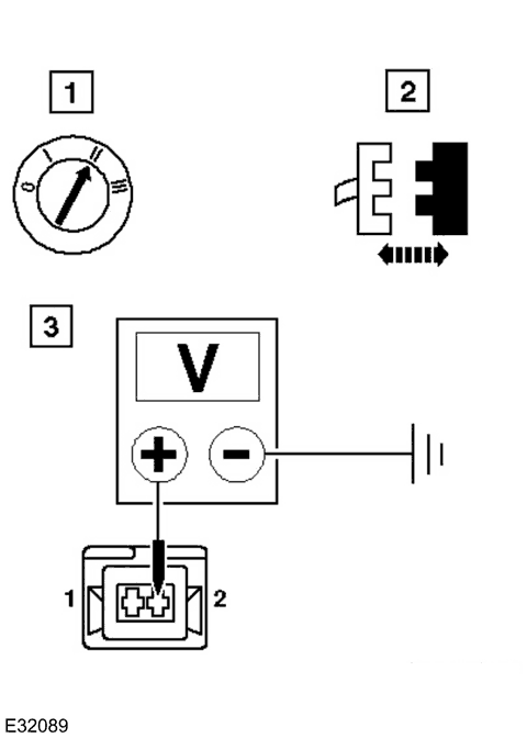
- Measure the voltage between PI032/002 and ground EM016L
B+ ?
Yes → GO to C5.
No → Inspect EM020/010 PI031 (PI032) for bent / pushed back pins or locate and repair harness / splice PIS06. Check fuse F12 is good and EMS control RELAY 1 energized. Test the system for normal operation.
Check harness short to ground
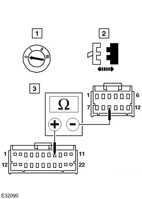
- With EM015 and EM014 disconnected, measure the insulation resistance between EM015/008 and ground EM014/009
Is the resistance > 10 MOHM?
Yes → Do not reconnect GO to C6.
No → Inspect EM015, and EM014 for corrosion, bent / pushed back pins or locate and repair the harness / connector. Test the system for normal operation.
Check harness short core to core
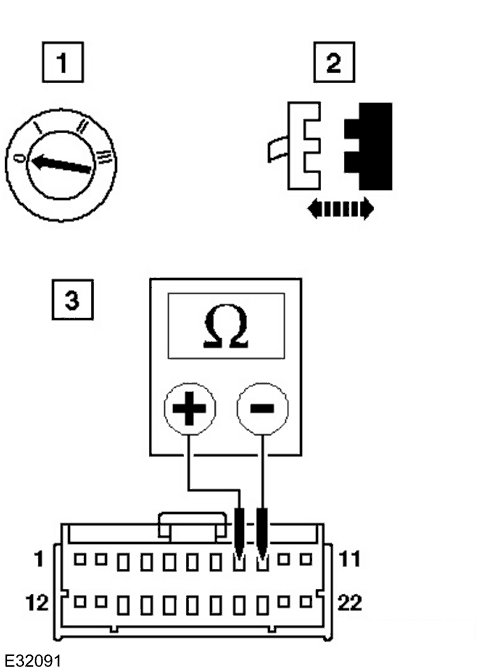
- With EM015, EM014, PI031 and PI032 disconnected, measure the insulation resistance between EM015/009 and EM015/008
Is the resistance > 10 MOHM?
Yes → Reconnect all connectors GO to C7.
No → Inspect EM015, PI031 and PI032 for corrosion, bent / pushed back pins or locate and repair the harness / connector PI001/016 or PI001/027. Test the system for normal operation.
Check harness continuity
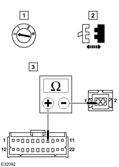
- With EM015 and PI032 disconnected, measure the resistance between EM015/008 and PI032/001
Is the resistance < 0.5 OHM?
Yes → GO to C8.
No → Inspect harness / connectors EM015, PI032 and PI001/027 for corrosion, damage, bent or pushed back pins and repair as required. Test the system for normal operation.
Check harness (ground) continuity
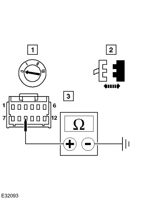
- With EM014 disconnected, measure the resistance between EM014/009 and ground EM016L
Is the resistance < 0.5 OHM?
Yes → Reconnect EM014, EM015, PI031 or (PI032) GO to C10.
No → Inspect harness / connector EM014, ground stud and splice EMS037 for corrosion, damage, bent or pushed back pins and repair as required. Test the system for normal operation.
Check mechanical condition
- Remove the VVT(s) and ensure that there is no foreign matter blocking the oil passageway
OK?
Yes → GO to C10.
No → Rectify as required
END
- Perform appropriate service drive cycle and check for the presence of DTC.
Has the fault code cleared?
Yes → STOP
No → Contact Jaguar Service
Parts & tools for this job For 1998 Jaguar XJ-8
- PARTEngine gasket setSearch: Jaguar XJ-8 1998 engine gasket set
- TOOLTorque wrenchSearch: 3/8 inch torque wrench
- TOOLFeeler gauge setSearch: feeler gauge set
Links open Amazon search results in a new tab. As an Amazon Associate I earn from qualifying purchases.