
303-01 Engine (Engine): Description and operation
- Make
- Jaguar
- Model
- XK-8 XK8 (X100) Factory Service Manual
- Year
- 1999
- Section
- 303-01 Engine › Description and operation › Engine
Engine
Cylinder Block
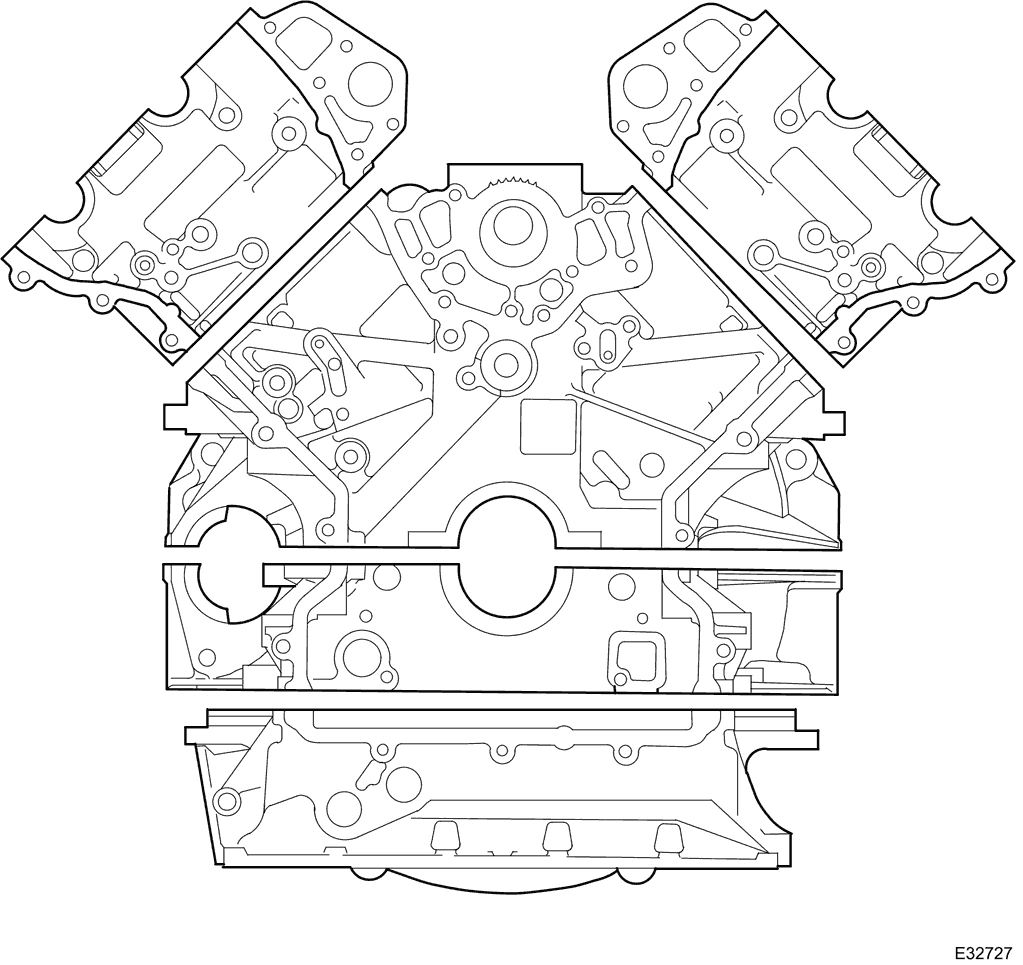
The cylinder block is of an enclosed 'Vee' design with 'Nikasil' plated cylinder bores to reduce piston friction, improve warm up and oil retention. A low volume coolant jacket improves warm up time and reduces piston noise levels.
Viewed from the driving position, the right-hand cylinder bank is designated A-bank and the left-hand cylinder bank as B-bank.
The cylinder bores of each bank are numbered 1 to 4, from the front of the vehicle.
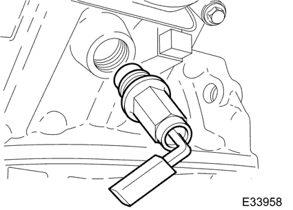
The coolant drain plug is located on the rear left side of the cylinder block.
On vehicles supplied with a cold climate package (i.e. vehicles operating in conditions regularly below -30°C) a cylinder block heater unit is fitted instead of the drain plug.
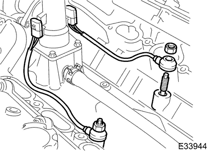
Two knock sensors are fitted to the cylinder block on the inboard side of each cylinder bank. The flying lead of each sensor is secured to a bracket on (or near to, depending on the model) the thermostat housing.
These piezo-electric sensors provide inputs to the ECM to indicate the detection and location of detonation during combustion.
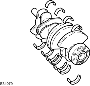
The cast iron crankshaft has undercut and rolled fillets for improved strength and six counter-balance weights ensure low levels of vibration from the four throw, five bearing configuration.
The main bearing shells are aluminium / tin split plain type. An oil groove in the top half of each bearing transfers oil into the crankshaft oilway drillings for lubrication of the connecting rod bearings. A lead/bronze thrust washer is fitted on each side of the top half of the center main bearing.
The crankshaft rear oil seal is lipped and is a press fit in the interface of the bedplate to cylinder block.
A torsional vibration damper and pulley assembly is bolted to the crankshaft nose.
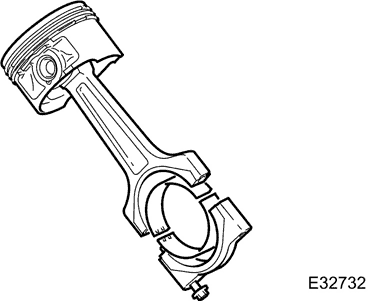
The connecting rods are manufactured from sinter-forged steel and have fracture-split bearing caps. The opposing sides of each connecting rod being fractured at the bearing horizontal center line.
The cylinder position is etched on adjoining sides of the joint to identify matching connecting rods and bearing caps. The connecting rod bearing shells are lead / bronze, split plain bearings.
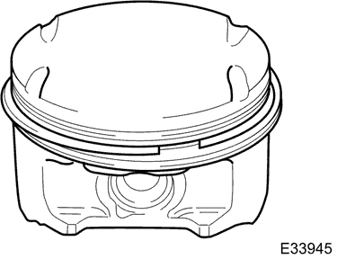
The pistons are open ended skirt design with flat upper surfaces (dished on supercharged engines) to reduce heat absorption. The piston crown has four cut-outs to clear the valve heads for any available combination of cam profile and valve phasing. Three piston rings, two compression and one oil control, are fitted to each piston. Each piston is fitted on a wrist pin which operates in a lead / bronze bush fitted in the connecting rod.
Timing Gear
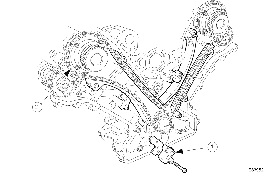
- 1 Primary Chain Tensioner
- 2 Primary Chain
Single row primary and secondary chains drive the camshafts of each cylinder bank. The primary chains transmit the drive from two sprockets on the crankshaft to a sprocket on each intake camshaft. The secondary chains transmit the drive from a second, smaller sprocket on the intake camshaft to a sprocket on the exhaust camshaft.
Each chain has a hydraulic tensioner operated by the engine lubricating system. A jet of oil from the end of each tensioner lubricates the chains. The primary chain tensioners act on pivoting flexible tensioner blades, the secondary chain tensioners act directly on the chains. Guide rails are used on the drive side of the primary chains.
A key locates the two drive sprockets on the crankshaft and these are retained in position by the crankshaft torsional vibration damper.
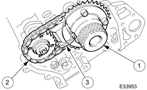
- 1 Variable Valve Timing Unit, where fitted
- 2 Secondary Chain
- 3 Secondary Chain Tensioner
The variable valve timing units and the exhaust camshaft sprockets are a non-interference, non-keyed fit on their respective camshafts. They are clamped in place on the camshafts by the securing bolt and clamping plate/washer.
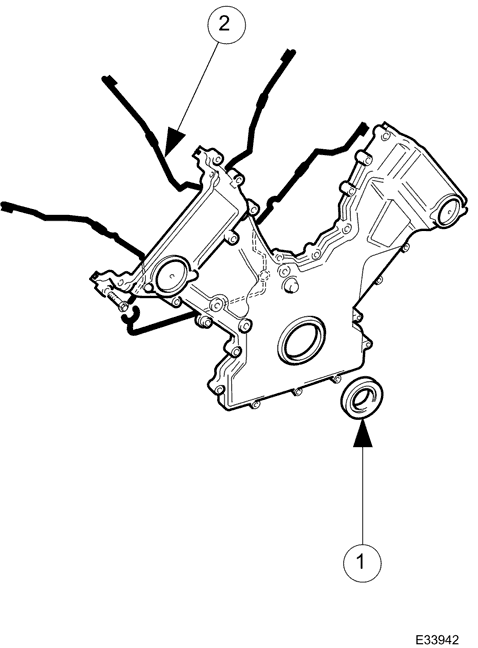
- 1 Crankshaft Front Oil Seal
- 2 Silicon Rubber Gaskets
The aluminium-alloy timing cover accommodates the crankshaft front oil seal. Silicon rubber in-groove gaskets seal the joint between the timing cover and the front face of the engine.
Cylinder Heads and Valve Gear
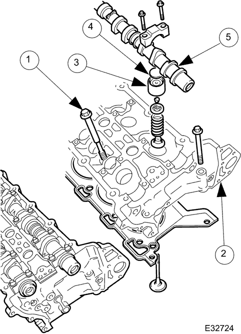
- 1 Cylinder Head Bolt
- 2 Lifting Eye
- 3 Valve Lifter
- 4 Adjustment Shim
- 5 Camshaft
Cylinder heads are unique to each cylinder bank and are secured, using deep seated bolts, to the cylinder block. Two hollow dowels align each cylinder head with the cylinder block.
Each cylinder head gasket consists of a silicon beaded composite gasket with metal eyelets for the cylinder bores.
Each cylinder head incorporates dual overhead camshafts operating four valves per cylinder via solid aluminium-alloy valve lifters. A steel shim in the top of each lifter allows adjustment of valve clearances.
Valve head diameter is 31 mm for exhaust and 35 mm for intake, and all valve stems are 5 mm diameter. Valve seats and guides are sintered metal inserts.
Collets, valve collars and spring seats locate the valve springs on the intake and exhaust valves. Valve stem seals are integrated into the spring seats.
Four 14mm spark plugs are located in a recess on the center-line of each cylinder head. For spark plug details refer to Section 303-07.
Camshafts
The chilled cast iron camshafts are each retained by five aluminium alloy caps - location numbers '0 to 4' for the intake camshaft and '5 to 9' for the exhaust, marked on the outer face of each cap.
A machined flat near the front of each camshaft enables the camshafts to be locked, using a special tool, during the valve timing procedure.
Camshaft Sensor
The camshaft sensor is a variable reluctance sensor that provides an input to the ECM of intake camshaft position.
On normally aspirated engines, a camshaft position sensor is mounted at the rear of each cylinder head on the inlet side and is triggered by a four toothed sensing ring, to provides four signals every 720 degrees of crankshaft rotation. The combination of signals from both sensors can indicate to the ECM when a particular piston is approaching TDC on the compression stroke, should it need to e.g. if a fault occured with the crankshaft position sensor. However, during normal operation, only the A-bank sensor is used in conjunction with the crankshaft sensor for normal fuelling and ignition functions.
On supercharged engines, one camshaft sensor is fitted to the rear of the B-bank cylinder head and is triggered by a single toothed sensing ring fitted to the rear of the intake camshaft.
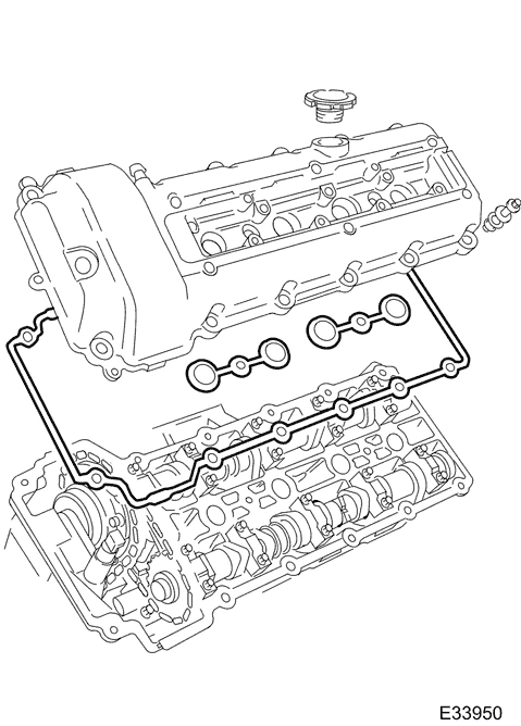
The camshaft covers are made from vinyl-ester plastic; the A-bank cover incorporates an outlet for the full load engine breather.
The B-bank cover incorporates the engine oil filler cap and an outlet for the part load engine breather. Identical oil separators are incorporated inside the top of each cover. Each oil separator comprises a wire gauze packing in an open ended enclosure below the breather outlet.
Lifting Eyes
There are four lifting eyes for the engine. One lifting eye is cast into the front of each cylinder head assembly and the rear lifting eyes, also one per cylinder head, are bolt-on special tools.
Bedplate
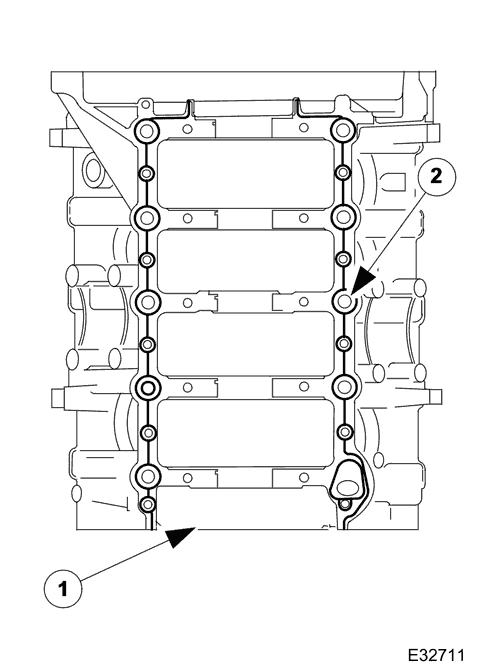
- 1 Bedplate
- 2 Sealant Track
This is a structural casting bolted to the bottom of the cylinder block to retain the crankshaft and to further improve overall rigidity.
Slight changes to main bearing clearance due to expansion are minimised by means of iron inserts cast into the bedplate main bearing supports.
Two hollow dowels align the bedplate with the cylinder block and the joint is sealed by a continuous bead of sealant.
The engine speed sensor is located at the rear of the bedplate and is a variable reluctance sensor that provides an input to the ECM representing engine crankshaft speed and position.
Intake Manifold (Normally Aspirated)
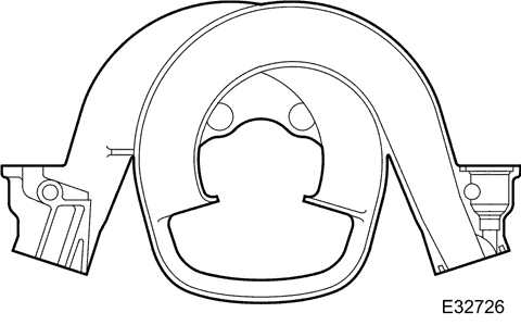
The intake manifold is manufactured in plastic with plastic integrated fuel rails and metal thread inserts; the very smooth internal surfaces give excellent air flow.
Individual ducts lead off a central chamber to the inlet valves of each cylinder.
Silicon rubber gaskets, located in channels in the intake manifold, seal the joints between the ducts and the cylinder heads.
Supercharged engines do not have a conventional manifold, but use an Intercooler Adaptor Assembly on each cylinder head to pass cooled air from the intake air charge coolers (one for each bank) to the engine intake. The fuel injectors and fuel rail are also located on each Intercooler Adaptor Assembly.
Induction Elbow
The induction elbow provides the interface between the electronic throttle and the intake manifold.
Connections on the induction elbow provide vacuum take-offs for various services.
A boss on the rear of the elbow accommodates the EGR valve - where fitted. On engines without EGR, the boss is closed by a blanking plate.
Exhaust Manifold
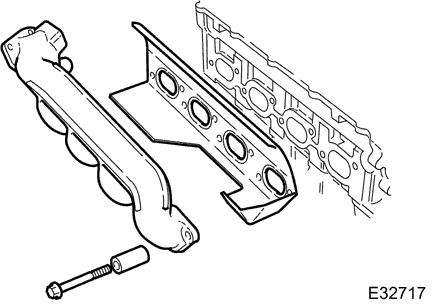
The thin walled cast iron manifolds are unique to each cylinder bank. On engines with Exhaust Gas Recirculation (EGR) (see Section 303-08) the A-bank manifold has a transfer pipe connection. Spacers on the securing bolts allow expansion and retraction upon temperature changes whilst maintaining clamping loads. Heat shields are integrated in the exhaust manifold gaskets.
Engine Mountings
The engine is mounted at three points. At the front, on each side of the engine, there is a mounting bracket with a Hydramount mounted to the crossbeam. At the rear, a single rubber / metal composite mount is fixed to the cast crossmember.
The rear engine mounting rubber provides support for the rear of the engine and the transmission unit. This is a rubber mount and metal bracket assembly secured with a single fixing onto the crossmember. This, in turn, is located on an extension bracket at the rear of the transmission unit.
The three mountings are non-serviceable items.
Engine Lubrication
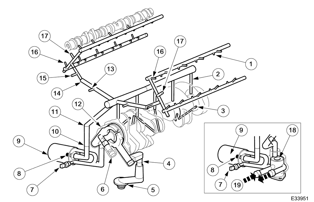
- 1 Valve Lifter Supply
- 2 Main Bearing Supply
- 3 Connecting Rod Bearing Supply
- 4 Bedplate/Cylinder Block Interface
- 5 Oil Pick-Up
- 6 Pressure Relief Valve
- 7 Oil Pressure Switch
- 8 Oil Temperature Switch
- 9 Oil Filter
- 10 Structural Sump/Bedplate Interface
- 11 Bedplate/Cylinder Block Interface
- 12 Oil Pump
- 13 Primary Chain Tensioner Supply
- 14 Cylinder Block/Cylinder Head Interface
- 15 Variable Valve Timing Supply
- 16 Camshaft Bearing Supply
- 17 Secondary Chain Tensioner Supply
- 18 Oil Diverter (Where fitted)
- 19 Oil Supply and Return
Oil is drawn from the reservoir in the oil pan and pressurized by the oil pump. The output from the oil pump is then filtered and distributed through the internal oil passages.
Where an oil cooler is fitted, the oil is cooled before entering the filter.
All moving parts are lubricated either by pressure or splash oil. Pressurized oil is also provided for operation of the variable valve timing units and the timing gear chain tensioners.
With the exception of the pump and the oil level gauge (dip stick), all of the oil system components are installed on the structural sump.
Oil is returned to the oil pan under gravity through large drain holes in the cylinder heads and the engine block to ensure quick return of the oil.
Oil Pick-Up
The plastic moulded oil pick-up is attached to the underside of the structural sump. It is immersed in the oil reservoir to provides a supply to the oil pump during all normal vehicle attitudes. A castellated inlet allows the supply to be maintained after any deformation of the sump pan (e.g. after grounding). A mesh screen in the inlet prevents debris from entering the oil system.
Oil Pressure Switch
Installed at the right front of the structural sump, the oil pressure switch connects a ground input to the instrument cluster when oil pressure is present. This switch operates at a pressure of 0,15 to 0,41 bar (2.2 to 5.9 lbf. in2).
Oil Temperature Switch
Installed at the right front of the structural sump adjacent to the pressure switch. Indicates to the Engine Control Module the temperature of the engine oil, for use in the variable valve timing computations.
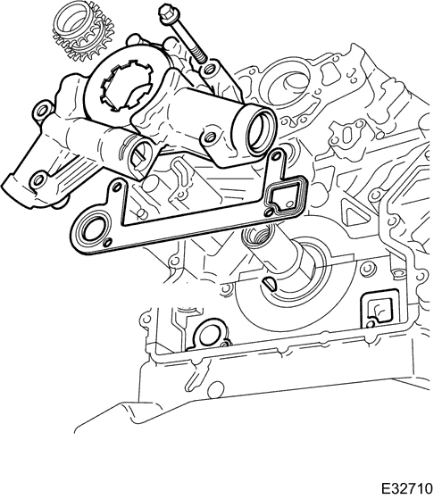
An uprated (higher capacity) oil pump is fitted to cope with the increased demands of the linear VVT system. The pump is located at the front of the engine and is driven directly by the crankshaft. The inlet and outlet ports align with oil passages in the bedplate, with a rubber coated metal gasket to seal the pump to bedplate interface.
An integral pressure relief valve regulates pump outlet pressure at 4,5 bar (65.25lbf/in2).
Oil Pan
The oil pan / sump comprises an aluminium-alloy structural sump bolted to the bedplate and a pressed steel pan with integral drain plug, bolted to the structural sump.
Oil is drawn from the oil reservoir in the oil pan, pressurized by the oil pump, cooled (on vehicles with an oil cooler), filtered and distributed through internal oil passages. Oil returns to the pan under gravity.
Oil Filter
A renewable canister type oil filter is fitted on the adapter which is located on the right-hand side of the structural sump towards the front of the engine. An internal bypass facility permits full flow bypass if the filter is blocked.
Oil Level Gauge (Dipstick)
The oil level gauge is located towards the front of the engine on the left side of the oil pan, supported in a tube fitted in the bedplate. The holes in the end of the oil gauge indicate minimum and maximum oil levels; approximately 1 liter difference.
Oil Filler Cap
The oil filler cap is located on the top of the B-bank camshaft cover.
Windage Tray
A windage tray attached to the top of the structural sump isolates the oil pan from the disturbed air flow, caused by the rotation of the crankshaft; preventing oil aeration and improving oil drainage.
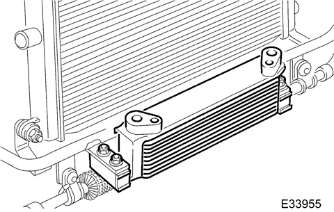
The engine oil cooler is located in front of the radiator, mounted off-center with two steady brackets bolted onto the front upper crossmember in front of the cooling module.
When an oil cooler is fitted, an oil diverter valve is also fitted onto the oil filter with supply and return piping to and from the oil cooler.
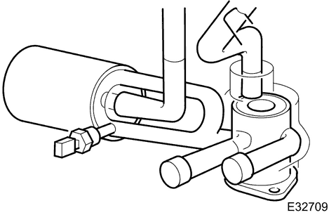
This valve is fitted between the oil pump outlet and the oil filter inlet.
The oil diverter valve operates thermostatically and at higher temperatures diverts the oil through the oil cooler. The valve begins to open between 103°C and 107°C and is fully open, diverting 100% of the oil, at 119°C.
Crankcase Ventilation
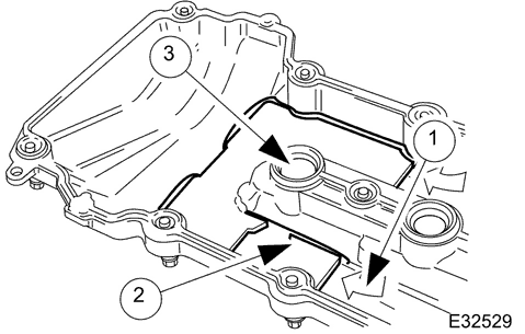
- 1 Oil Entry Point
- 2 Wire Gauze
- 3 Breather Outlet
The engine is ventilated through a part-load and a full-load breather; one on each camshaft cover. These flexible plastic hoses incorporate O-ring seals and quick release connectors.
The part-load breather ventilates the left-hand camshaft cover (B-bank) and feeds onto the throttle body adaptor and the purge valve. This breather is connected between the oil separator in the cover and the induction elbow.
The full-load breather ventilates the right-hand cover (A-bank) and is connected between the oil separator in the cover and the air intake duct between the mass air flow sensor (MAFS) and the throttle body.
The MAFS unit combines the two sensors: one for air flow and one for air inlet temperature. It is a hot wire sensor that provides an input which is (approximately) proportional to the mass air flow into the engine.
Each camshaft cover oil separator consists of wire gauze packed into an open ended enclosure in the top of the cover, below the breather outlet.
Engine Covers
Engine covers are fitted over the fuel injectors on each cylinder bank and are isolated from the engine by rubber grommets to prevent noise.
Block Dowels, Block Plugs and Stub Pipe
A shaped plug / cover, known as the 'Valley' plug, is fitted to the top of the engine block at the centre of the 'Vee' formed by the angle between the 'A' and 'B' banks of the cylinder block.
Ring dowels
Ring dowels are used as follows:
To assist in the location / installation of each cylinder head to its respective location on the block.
Two are used to locate the main sump body to the cylinder block.
Two are used at the rear of the engine block to locate the mating face of the transmission housing.
Two are fitted into the casting at the front, one on each side, to locate and align the timing cover and two more each side of the front face to locate the VVT bush carriers (where fitted).
Two are fitted each side near the front to locate the accessory mounting bracket and the generator mounting bracket.
Block Plugs
Two core plugs are fitted in the rear face of the engine block.
Three flanged, threaded plugs with micro-encapsulated sealant and a sealing washer are fitted, one into the front face of the block behind the water pump, one to the rear face adjacent to the two core plugs and one to the rear of the left hand side.
Stub Pipe
A stub pipe in the centre of the raised part of the block casting for the thermostat housing, accommodates one end of the heater return hose.
Engine Sealing
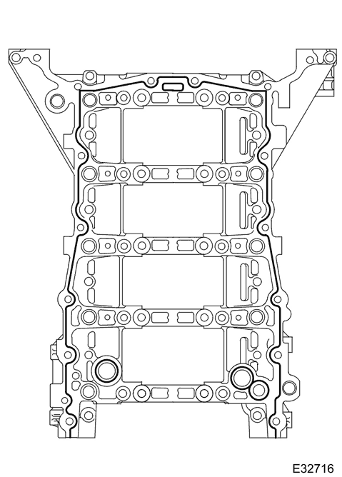
Three types of sealing methods are used on the engine:
a) In-groove seals.
b) Edgebond metal carrier gaskets.
c) Formed-in-place (FIP) liquid sealant.
For a) and b) the seals are to be renewed if the mating components are disturbed during service i.e. they are not re-usable.
For c) no general servicing is required - sealant/joint designed for service life of engine (must be renewed if the mating components are disturbed).
Two types of FIP sealant are used:
Anaerobic (Loctite 648): used on core plugs and block stub pipe.
RTV silicone sealant (Loctite 5699 Ultra Grey): used on block-to-bedplate and sump-to-bedplate joints. Designed service life is 150,000 miles.
Ignition System
The ignition system consists of eight ignition coils, one per spark plug, each incorporating an amplifier module which is controlled by one of two outputs from the ECM. Each output of the ECM controls four of the spark plug mounted ignition coils, two on each bank.
The 14mm spark plugs, one per cylinder, locate in recesses along the center-line of each cylinder head. The on-plug ignition coils are secured to the camshaft covers and each on-plug coil has its own plastic cover.
Variable Valve Timing (VVT)
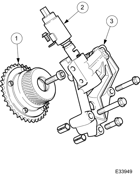
- 1 Variable Valve Timing (VVT) Unit
- 2 Solenoid / Shuttle Valve
- 3 Bush Carrier
For each intake camshaft there is a variable valve timing unit, a bush carrier assembly and a solenoid / shuttle valve.
It is an infinitely variable system (within the prescribed operating range) operating on the intake camshafts only. There is the equivalent of 48° of crankshaft movement between the retarded and advanced positions. Engine oil pressure operates the system under the control of the ECM.
The variable valve timing system improves both low speed and high speed engine performance, engine idle quality and exhaust emissions. Engine idle is improved due to the ECM being able to retard the valve timing by an additional 10° compared to the previous VVT system; this also reduces the internal EGR at idle, where it is not required. However, the internal EGR system is improved at normal engine running speeds to reduce NOx emission and eliminate the need for any external EGR system components.
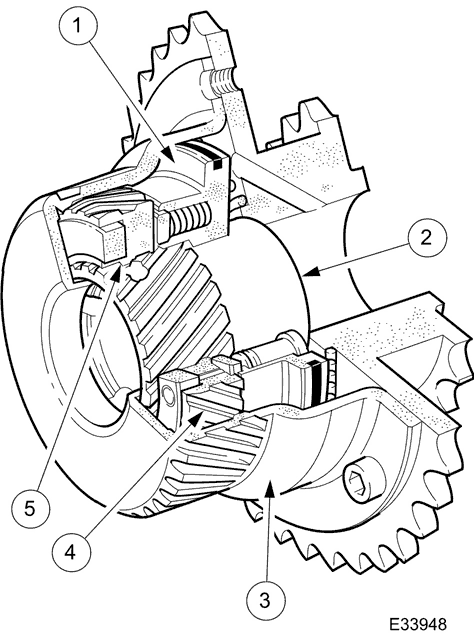
- 1 Ring Piston
- 2 Inner Sleeve
- 3 Body and Sprocket Assembly
- 4 Helical Gears - Piston to Body
- 5 Helical Gears - Piston to Inner Sleeve
The valve timing unit turns the intake camshaft relative to the primary chain to advance or retard the timing.
The unit consists of a body and sprocket assembly separated from an inner sleeve by a ring piston and two helical ring gears; the inner sleeve is bolted to the camshaft.
The two helical ring gears are part of the cylindrical extention of the piston, one gear on the outer bore (meshing with the helical gear which is on the inner bore of the body and sprocket assembly) and one on the inner bore (meshing with the inner sleeve).
As engine oil pressure moves the piston in the advance direction (to the right on the illustration) the helical ring gear on the outer bore of the piston causes the whole piston assembly to turn to the right as well as moving to the right. In the same way, the movement of the piston to the right, combined with the rotation caused by the outer helical gear assembly, causes the inner sleeve and hence the camshaft to rotate to the right in the advanced direction. The procedure is identical, but in the opposite direction for retarding the timing.
A light bias spring in the retard direction is provided along with anti-backlash springs.
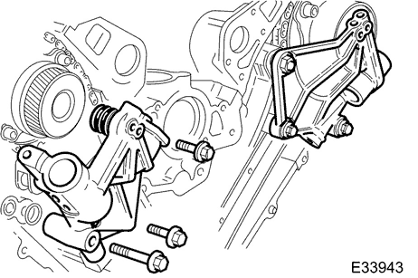
This contains the oil passages that link the engine oil supply from the cylinder block gallery to the variable valve timing (VVT) unit. A lug on the bush carrier locates in the central bore of the VVT unit.
Two hollow dowels at the bush carrier and cylinder block ensure that the lug is accurately located within the valve timing unit. O-rings seal the joint between the lug and the valve timing unit.
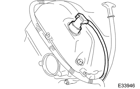
The VVT solenoid / shuttle valve assembly is bolted to the bush carrier and protrudes through the camshaft cover. Electrical connection to the solenoid is from the engine harness.
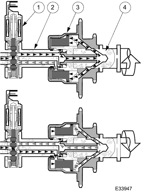
- 1 Solenoid / Shutle Valve Assembly
- 2 Bush Carrier
- 3 Variable Valve Timing Unit
- 4 Intake Camshaft
The valve timing solenoid controls the position of the shuttle valve relative to the two ports in the bush carrier.
The shuttle valve, depending on its position set by the solenoid at any instant, directs engine oil pressure to either the retard side or the advance side of the piston assembly.
The position of the solenoid / shuttle valve is controlled by a return spring and a 300 Hz pulse-width-modulated signal provided by the ECM.
Parts & tools for this job For 1999 Jaguar XK-8
- PARTEngine gasket setSearch: Jaguar XK-8 1999 engine gasket set
- TOOLTorque wrenchSearch: 3/8 inch torque wrench
- TOOLFeeler gauge setSearch: feeler gauge set
Links open Amazon search results in a new tab. As an Amazon Associate I earn from qualifying purchases.