
Commander 4WD V8-4.7L VIN N (2006)
Steering Mounted Controls Communication Module: Description and Operation
MODULE-STEERING CONTROL
DESCRIPTION
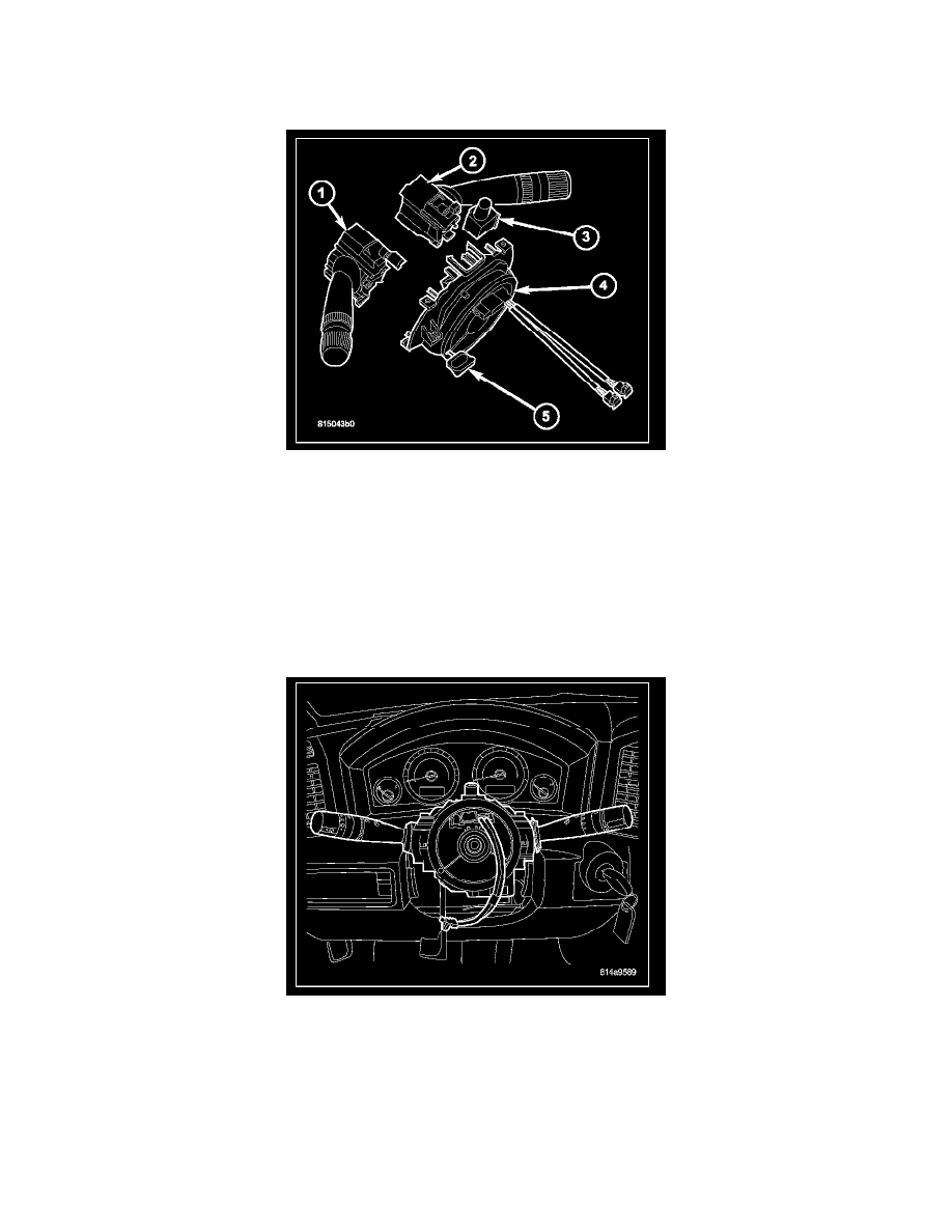
This vehicle is equipped with a Steering Control Module (SCM) (4) that houses an integral, internal clock-spring. On some vehicles, the SCM also
includes an integral, internal Steering Angle Sensor (SAS). The SCM is secured near the top of the steering column below the steering wheel and is
completely concealed beneath the steering column shrouds. The SCM is installed as a modular unit that supports the left (lighting) multi-function switch
(1), the right (wiper) multifunction switch (2), the hazard switch (3) and the turn signal cancel cam. The controls for each of the switches extend through
appropriate clearance holes provided in the steering column shrouds.
The microprocessor-based SCM utilizes integrated circuitry and information carried on the Controller Area Network (CAN) data bus along with several
hard wired analog and multiplexed inputs to monitor both the right and left multi-function switches, the ignition switch, the horn switch, the speed
control switches and the remote radio switches. In response to those inputs, the internal circuitry and programming of the SCM allow it to control and
integrate many electronic functions and features of the vehicle through both hard wired outputs and the transmission of electronic message outputs to
other electronic modules in the vehicle over the CAN data bus.
The SCM circuitry, the clockspring, and the SAS are all contained within a flat, round molded plastic case. The back (instrument panel side) of the case
has an integral mounting bracket that is secured to the stationary steering column housing with two screws. The back of the case also features a total of
five integral fixed connector receptacles. The three upper receptacles are direct interface connectors for the hazard and multi-function switches and are
concealed when these switches are mounted. The two lower receptacles connect the SCM to the vehicle electrical system through two take outs and
connectors of the instrument panel wire harness.
The face of the SCM case consists of the rotating clockspring rotor with two integral connector receptacles and two pigtail wires with connectors located
near the top. One receptacle receives the connector from the remote radio switches, and the other receives the connector from the horn switch and the
speed control switches. The two pigtail wires contain the multistage driver airbag squib circuits. The turn signal cancel cam (not shown) extends from the
back of the SCM case but is secured to the hub of the clockspring rotor and is keyed to the steering shaft so that it rotates the clockspring rotor with the