
Commander 4WD V8-4.7L VIN N (2006)
Steering Mounted Controls Communication Module: Service and Repair
MODULE-STEERING CONTROL
WARNING: TO AVOID PERSONAL INJURY OR DEATH, ON VEHICLES EQUIPPED WITH AIRBAGS, DISABLE THE
SUPPLEMENTAL RESTRAINT SYSTEM BEFORE ATTEMPTING ANY STEERING WHEEL, STEERING COLUMN, AIRBAG,
OCCUPANT CLASSIFICATION SYSTEM, SEAT BELT TENSIONER, IMPACT SENSOR, OR INSTRUMENT PANEL COMPONENT
DIAGNOSIS OR SERVICE. DISCONNECT AND ISOLATE THE BATTERY NEGATIVE (GROUND) CABLE, THEN WAIT TWO
MINUTES FOR THE SYSTEM CAPACITOR TO DISCHARGE BEFORE PERFORMING FURTHER DIAGNOSIS OR SERVICE. THIS IS
THE ONLY SURE WAY TO DISABLE THE SUPPLEMENTAL RESTRAINT SYSTEM. FAILURE TO TAKE THE PROPER
PRECAUTIONS COULD RESULT IN ACCIDENTAL AIRBAG DEPLOYMENT.
CAUTION: A service replacement Steering Control Module (SCM) is shipped with the clockspring pre-centered and with a molded plastic locking pin
installed. This locking pin should not be removed until the SCM has been installed on the steering column. If the locking pin is removed before the SCM
is installed on a steering column, the clockspring centering procedure must be performed.
NOTE: Before starting this procedure, be certain to turn the steering wheel until the front wheels are in the straight-ahead position and that the entire
steering system is locked or inhibited from rotation.
REMOVAL
1. Place the front wheels in the straight ahead position.
2. Disconnect and isolate the battery negative cable.
3. Remove the driver airbag from the steering wheel.
4. Disconnect the steering wheel wire harness connectors from the upper clockspring rotor connector receptacles.
CAUTION: Be certain that the screws that secure the steering wheel puller to the steering wheel are fully engaged in the steering wheel armature
without passing through the steering wheel and damaging the clockspring.
5. Remove the steering wheel from the steering column.
6. Remove the shrouds from the steering column.
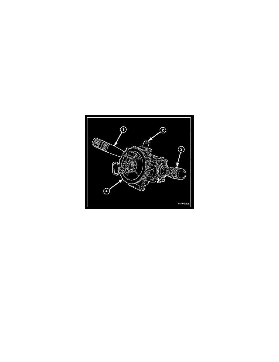
7. Remove the right (wiper ) multi-function switch (3) from the SCM (4).
8. Remove the left (lighting) multi-function switch (1) from the SCM.
9. Remove the hazard switch (2) from the SCM.