
Wrangler L6-4.0L VIN S (2000)
Cigarette Lighter Relay: Testing and Inspection
Accessory Relay
The accessory relay is located in a wire harness connector that is secured to the 100-way connector bracket under the driver side of the instrument panel,
near the cowl side inner panel in the passenger compartment. For complete circuit diagrams, refer to Horn/Cigar Lighter in the Contents of Wiring
Diagrams.
WARNING: ON VEHICLES EQUIPPED WITH AIR-BAGS, REFER TO AIR BAGS AND SEAT BELTS/AIR BAGS BEFORE
ATTEMPTING ANY STEERING WHEEL, STEERING COLUMN, OR INSTRUMENT PANEL COMPONENT DIAGNOSIS OR SERVICE.
FAILURE TO TAKE THE PROPER PRECAUTIONS COULD RESULT IN ACCIDENTAL AIR-BAG DEPLOYMENT AND POSSIBLE
PERSONAL INJURY.
1. Remove the accessory relay from its wire harness connector. Refer to Accessory Relay for the procedures.
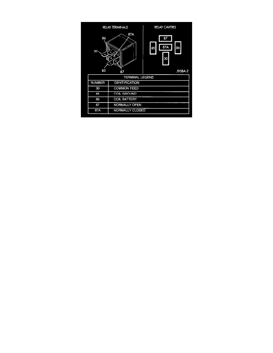
2. A relay in the de-energized position should have continuity between terminals 87A and 30, and no continuity between terminals 87 and 30. If OK,
go to Step 3. If not OK, replace the faulty relay.
3. Resistance between terminals 85 and 86 (electromagnet) should be 75 ± 5 ohms. If OK, go to Step 4. If not OK, replace the faulty relay.
4. Connect a battery to terminals 85 and 86. There should now be continuity between terminals 30 and 87, and no continuity between terminals 87A
and 30. If OK, perform the Relay Circuit Test that follows. If not OK, replace the faulty relay.
Relay Circuit Test
1. The relay common feed terminal (30) is connected to battery voltage and should be hot at all times. Check for battery voltage at the fused B(+)
circuit cavity of the accessory relay wire harness connector. If OK, go to Step 2. If not OK, repair the fused B(+) circuit to the fuse in the Power
Distribution Center (PDC) as required.
2. The relay normally closed terminal (87A) is connected to terminal 30 in the de-energized position, but is not used for this application. Go to Step
3.
3. The relay normally open terminal (87) is connected to the common feed terminal (30) in the energized position. This terminal supplies battery
voltage to the cigar lighter when the relay is energized by the ignition switch. There should be continuity between the accessory relay wire harness
connector cavity for relay terminal 87 and the accessory relay output circuit cavity in the cigar lighter wire harness connector at all times. If OK,
go to Step 4. If not OK,repair the open accessory relay output circuit to the cigar lighter wire harness connector as required.
4. The coil battery terminal (86) is connected to the electromagnet in the relay. The accessory relay wire harness connector cavity for this terminal
should have continuity to ground at all times. If OK, go to Step 5. If not OK, repair the open ground circuit to ground as required.
5. The coil ground terminal (85) is connected to the electromagnet in the relay. It receives battery feed to energize the accessory relay when the
ignition switch is in the Accessory or On positions. Turn the ignition switch to the On position. Check for battery voltage at the fused ignition
switch output (ace/run) circuit cavity of the accessory relay wire harness connector. If not OK, repair the open fused ignition switch output
(ace/run) circuit to the ignition switch as required.