
Rio5 L4-1.6L (2006)
CAUTION: Never use a self-powered test lamp on circuits that contain solid state modules. Damage to these modules may result.
An ohmmeter can be used in place of a self-powered test lamp.
The ohmmeter shows how much resistance there is between two points along a circuit. Low resistance means good continuity.
Circuits which include any solid-stale devices should be tested only with a 10-megaohm or higher impedance digital multimeter. When measuring
resistance with a digital multimeter, the battery negative terminal should be disconnected. Otherwise, there may be incorrect readings. Diodes and
solid-state devices in a be circuit can make an ohmmeter give a false reading. To find out if a component is affecting a measurement, take one reading,
reverse the leads and take a second reading.
If different the solid-state device is affecting the measurement.
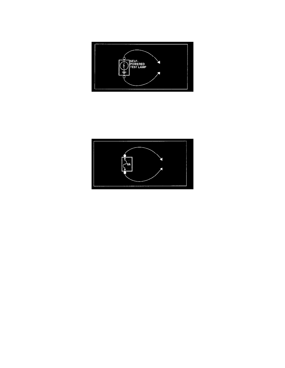
JUMPER WIRE WITH FUSE
Use a jumper wire with a fuse to by-pass an open circuit.
A jumper wire is made up of an in-line fuse holder connected to a set of test leads. This tool is available with small clamp connectors providing adaption
to most connectors without damage.
CAUTION: Do not use a fuse with a higher rating than the specified fuse that protects the circuit being tested. Do not use this tool in any situation to
substitute an input or output at the solid-state control module, such as ECM, TCM, etc.
SHORT FINDER
A short finder is available to locate a short to ground. The short finder creates a pulsing magnetic field in the shorted circuit and shows you the location
of the short through body trim or sheet metal.
TROUBLESHOOTING TEST
1. TESTING FOR VOLTAGE
This test measures voltage in a circuit. When testing for voltage at a connector, you do not have to separate the two halves of the connector.
Instead, probe the connector from the back(backprobe). Always check both sides of the connector because dirt and corrosion between its contact
surfaces can cause electrical problems.