
Rondo V6-2.7L (2009)
1. Pages by system/Name of schematic diagram
-
Each schematic diagram provides data related to current flow, switch functionality (Where applicable), and related circuit information.
-
Understanding circuit operation is a critical component of effective diagnosis.
-
The schematic diagram index provides a guide to locating the correct circuit.
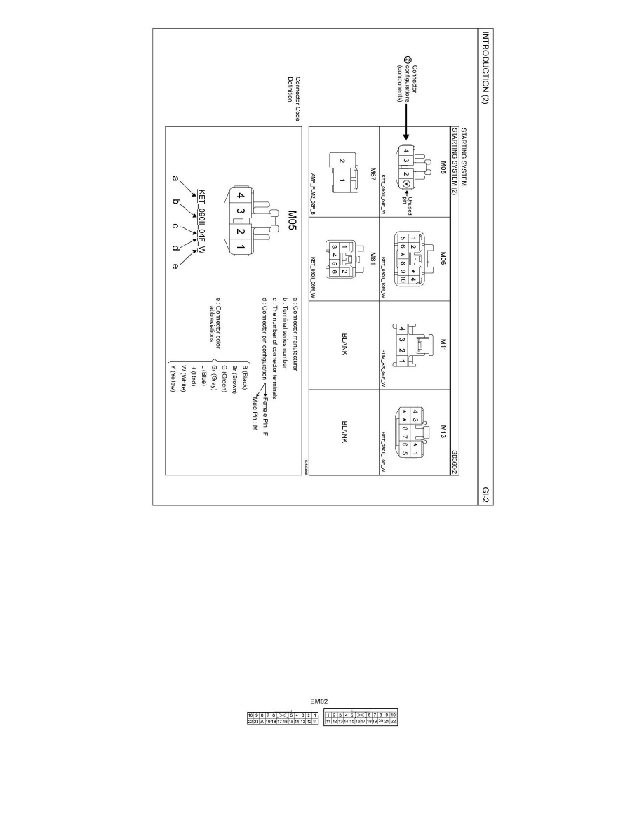
2. Connector configuration (components)
-
The pages following the schematic diagrams contain data related to component connector configuration. Each page shows a terminal side view
of the connector. Refer to the "Connector View and Numbering Order" section in this document for information related to terminal numbering.
NOTE: a "*" symbol in place of a terminal number indicates an unused terminal(connector cavity will be empty).
3. Connector Configurations (connection between harnesses)
-
The "Connector Configurations" section identifies connectors that are used to join harnesses together; junction connectors for common power
and ground wires are also identified in this section. Male and Female connector views are shown where applicable.
4. Component locations
-
schematic diagrams include references to images found in the "Component Locations" section of this document. These images show
components and connectors in their installed location on the vehicle