
Sedona EX V6-3.5L (2002)
Electronic Brake Control Module: Service and Repair
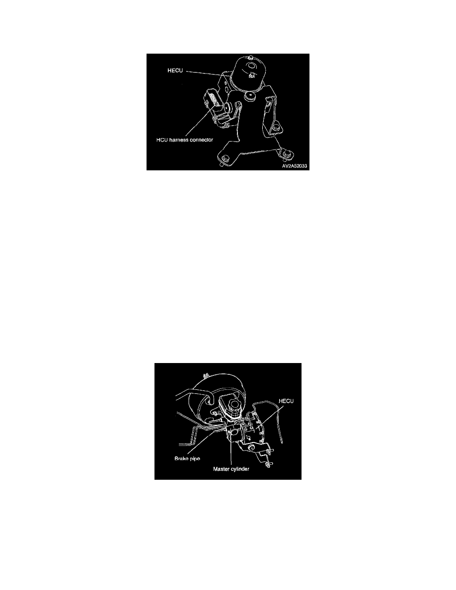
Removal
1. Turn ignition "OFF".
2. Disconnect ECU harness connector from ECU assembly.
Caution: Do not apply a 12V power source to any terminal of the ECU connector when disconnected.
3. Mark the brake pipes going into and out of the HCU with tags so reinstallation of the brake lines will be correct.
Caution: Before removing the brake pipes from HCU, the HCU must be thoroughly cleaned to prevent dirt particles from falling into the ports of
HCU or entering the brake pipes.
4. Remove the brake pipes from the HCU.
5. Loosen the mounting pin and grommet from HECU bracket and then remove HECU from HECU bracket.
6. Remove bolts attaching the ECU to the HCU.
7. Lift the ECU assembly straight from the HCU.
8. Clean the top of the HCU with a clean, dry cloth.
Replacement
1. Lower ECU onto the HCU and tighten its bolts to specification.
Tightening torque: 1.3 - 1.4 ft. lbs. (1.7 - 1.9 Nm. 0.18 - 0.2 kg-m)
2. Carefully place HECU to the HECU bracket.
3. Tighten the mounting pin and grommet to the HECU bracket
Tightening torque: 5.8 - 7.2 ft. lbs. (7.8 - 9.8 Nm, 0.8 - 1 kg-m)
4. Reconnect six brake lines. Be certain that the four outlet lines have been connected to the correct ports. Tighten the nuts to specification.
Tightening torque: 9.4 - 15.9 ft. lbs. (12.8 - 21.6 Nm, 1.3 - 2.2 kg-m)
Notice: When installing the brake pipe lines on the HCU valve block, they must be located correctly in the valve block to ensure proper ABS
operation.
5. Connect the ECU harness connector to ECM assembly.
6. Bleed the base brakes.
7. Road test vehicle to ensure proper operation of the base and ABS systems.