
Sedona EX V6-3.5L (2002)
Oxygen Sensor: Testing and Inspection
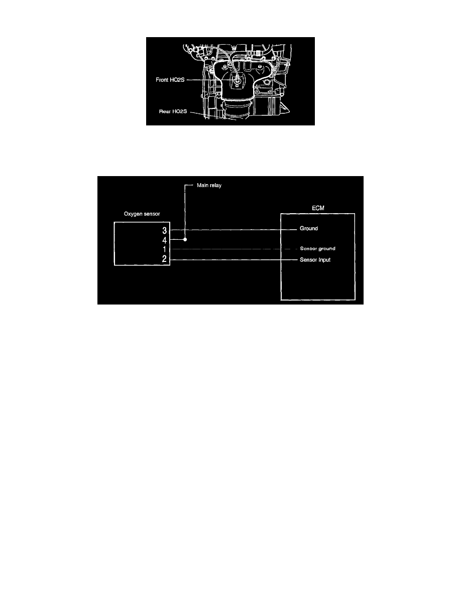
The heated oxygen sensor senses the oxygen concentration in exhaust gas, converts it into a voltage, which is sent to the ECM. The oxygen sensor
outputs about 1 V when the air fuel ratio is richer than the theoretical ratio, and outputs about 0 V when the ratio is leaner (higher oxygen concentration
in exhaust gas.). The ECM controls the fuel injection ratio based on this signal so that the air fuel ratio is maintained at the theoretical ratio. The oxygen
sensor has a heating element which ensures the sensor performance during all driving conditions.
Oxygen Sensor Configuration And Circuit Diagram
The basic principle of the operation of titania sensor is that, when the oxygen concentration from the exhaust emission manifold reduces (RH) , the
volume of O2 and the electronic concentration value will increase to make the titania element resistance reduce and, reversely, when the oxygen
concentration increases (leaner), the resistance will increase.
Accordingly, the ohm value of above 100 kOhms is regarded as corresponding leaner condition and the value below 100 kK Ohm0m as richer
condition.
The main point to check the oxygen sensor output function is to check the output voltage for being 0.1 - 0.9 V and the frequency 1.1 Hz at the
engine rate of 3000 rpm after full warming up.
The point of service is to check that the frequency is about 1.1 Hz while checking the output is also important.
Troubleshooting hints
1. Excessive exhaust gas will be emitted when the oxygen sensor is faulty.
2. Check the parts as below when the sensor output value is out of the specified range even though the sensor is in normal condition.
-
Incomplete injector
-
Air leakage from intake manifold
-
Incomplete air flow sensor, intake air temperature sensor and engine coolant temperature sensor.
-
Exhaust leakage