
Sedona EX V6-3.5L (2002)
Electronic Brake Control Module: Description and Operation
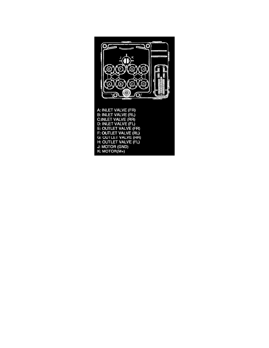
ELECTRONIC CONTROL UNIT (ECU)
Introduction
The electronics and microprocessor are integrated with the solenoid coils inside a Coil Integrated Module. The ECU is mounted directly to the
hydraulic control unit. The coils are used to operate the HCU valves during an ABS event. The ECU has circuits that monitor system status.
Self monitoring functions
The ECU monitors the components of the system for faults. If a fault is detected, the ABS system will set a Diagnostic Trouble Code (DTC) and
illuminate the amber ABS & EBD lamp, causing the ABS or EBD to be disabled. Although the ABS or EBD is inhibited, conventional brakes remain.
When the ignition switch is placed in the run position, the ECU will perform a preliminary self check on the anti-lock electrical system indicated by an
illumination of the amber ABS or EBD warning lamp in the instrument cluster.
Solenoid valve control
Solenoid valve operates when one side of valve coil applies positive voltage through valve relay and the other side connects to ground by MOSFET.
When valve relay turns ON and MOSFET turns ON by processor signal, concerned solenoid valve operates.