
Sportage 4WD L4-2.0L (2005)
-
The figures following the schematic diagrams contain data related to component connector configuration. Each figure shows a terminal side
view of the connector. Refer to the "Connector View and Numbering Order" in this document for information related to terminal numbering.
NOTE: a "*" symbol in place of a terminal number indicates an unused terminal (connector cavity will be empty).
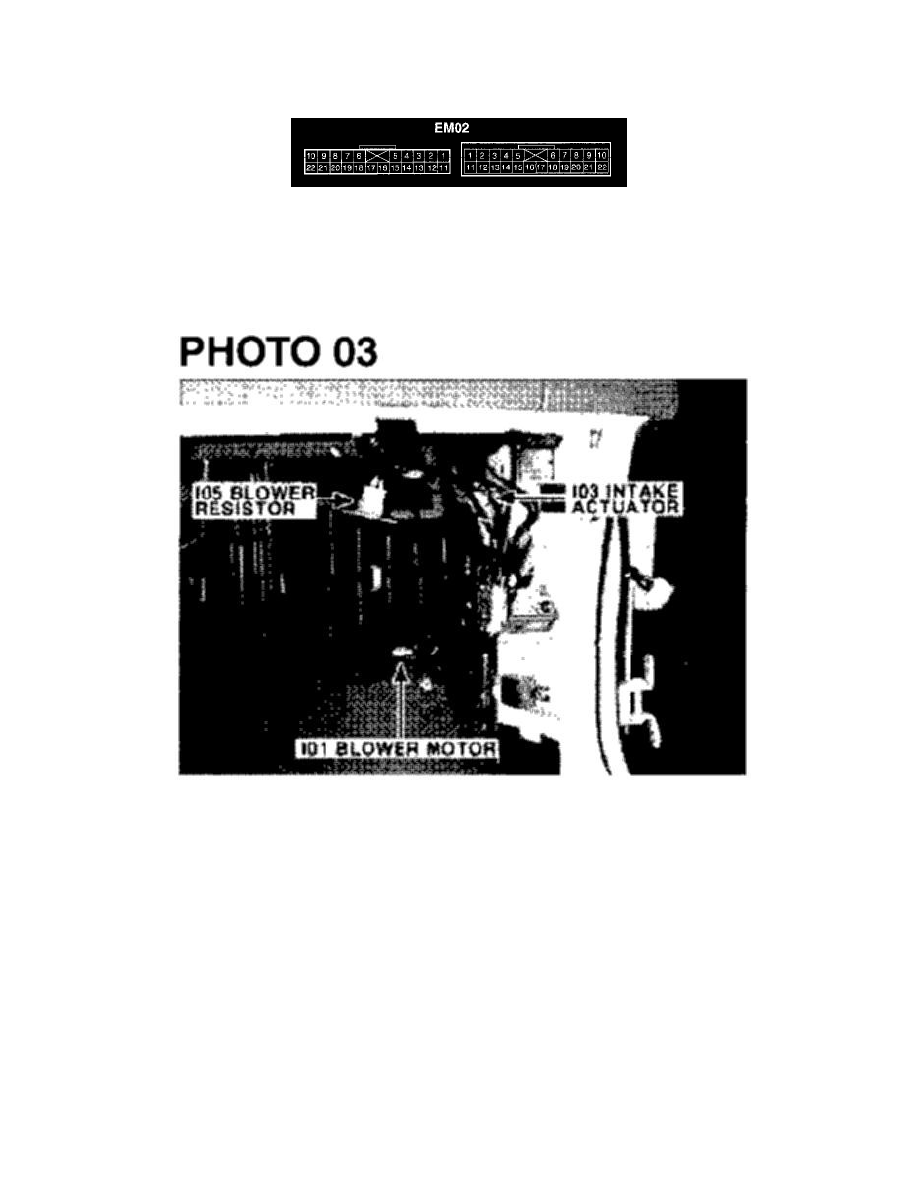
EM02
3. Connector configurations (connection between harnesses)
-
The "Connector Configurations" identifies connectors that are used to join harnesses together; junction connectors for common power and
ground wires are also identified. Male and female connector views are shown applicable.
4. Component locations
-
Schematic diagrams include references to images found in the "Component Locations". These images show components and connectors in
their installed location on the vehicle.