
Sportage 4WD L4-2.0L (2005)
1 MOhm or Higher -> Normal Circuit
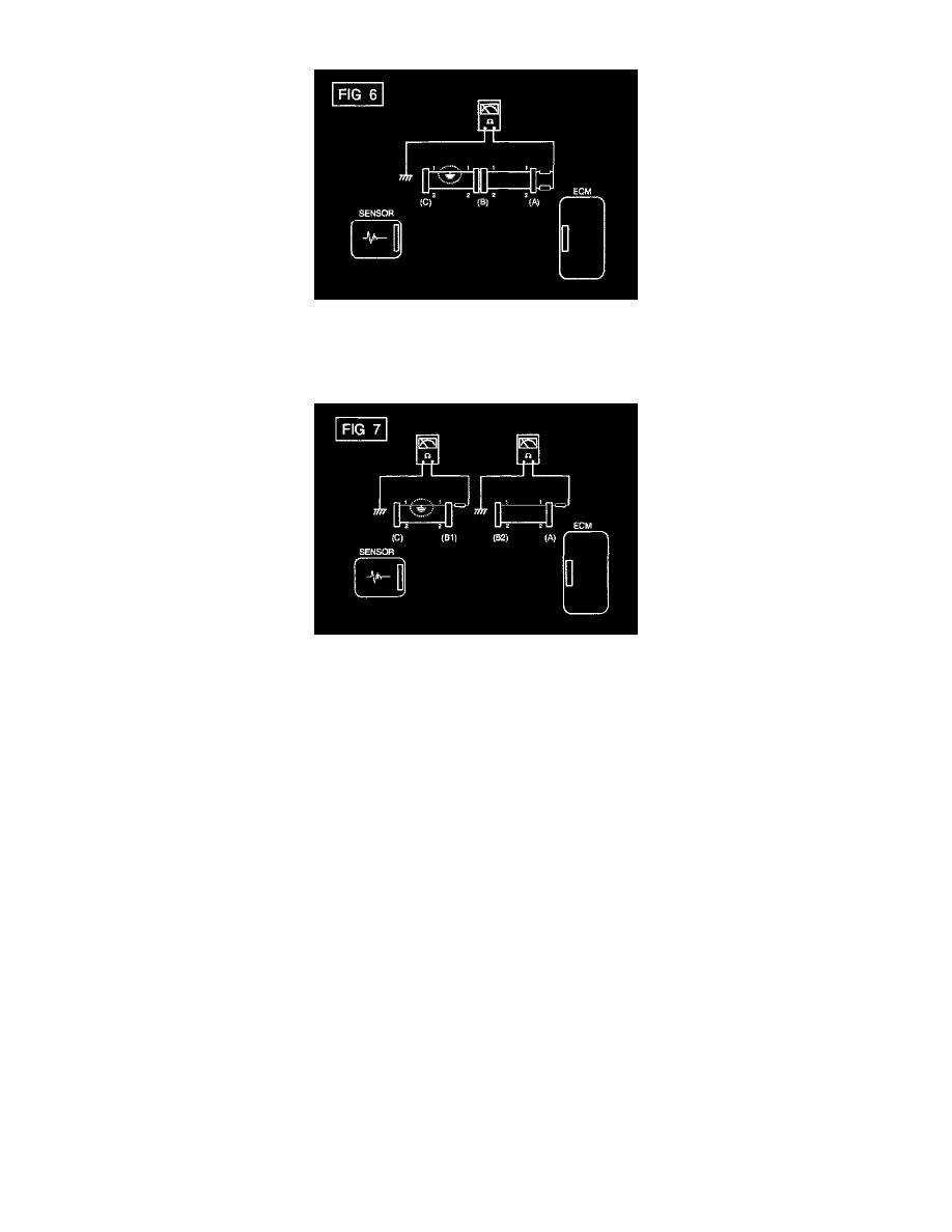
a. Disconnect connectors (A), (C) and measure for resistance between connector (A) and Chassis Ground as shown in [FIG 6]
The measured resistance of line 1 and 2 in this example is below 1 Ohm and higher than 1 MOhm respectively Specifically the short to
ground circuit is line 1 (Line 2 is normal) To find exact broken point, check the sub line of line 1 as described in the following step
b. Disconnect connector (B), and measure the resistance between connector (A) and chassis ground, and between (B1) and chassis ground as
shown in [FIG. 7]
The measured resistance between connector (B1) and chassis ground is 1 Ohm or less The short to ground circuit is between terminal 1 of
connector (C) and terminal 1 of connector (B1)