
Sportage 4WD L4-2.0L DOHC (1996)
The ground symbol (dot and 3 lines) (4) overlapping the component means the housing of the component is grounded to the vehicle frame or to a metal
part connected to the frame.
Connector Classification
The general location of connectors can be identified by using the chart below. The specific location of each connector can be found in the component
location photographs.
Connector ............................................................................................................................................................................................................... Location
C100 thru C199 ..................................................................................................................................................................................... Engine compartment
C200 thru C299 ........................................................................................................................................................................................... Instrument panel
C300 thru C399 .............................................................................................................................................................................. Passenger's compartment
C400 thru C499 ................................................................................................................................................................................. Luggage Compartment
C500 thru C599 .............................................................................................................................................................................................. Left front door
C600 thru C699 ............................................................................................................................................................................................ Right front door
C700 thru C799 ................................................................................................................................................................................................ Left rear door
C800 thru C899 .............................................................................................................................................................................................. Right rear door
C900 ...................................................................................................................................................................................................................... Headliner
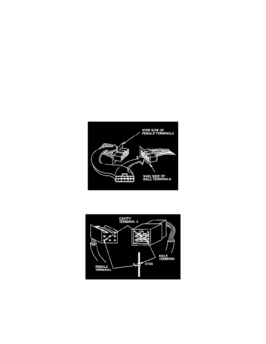
Connector Terminal Identification
The cavities (and wire terminals) in each connector are numbered starting from the upper right looking at the male terminals from the terminal side (or
looking at the female terminals from the wire side. Both views are in the same direction so the numbers are the same.) All cavities are numbered, even if
they have no wire terminals in them.
The connector cavity number is listed next to each terminal on the circuit schematic. The cavity/terminal shown is #4.
Harness Connector Views