
Gear engagement CABLE - R.R.
- Make
- Lancia
- Model
- Thesis Factory Service Manual
- Year
- 2002–2009
- Section
- Automatic transmission external controls › Gear engagement CABLE - R.R.
Gear engagement CABLE - R.R.
Removing
- Position the vehicle on a lift.
- Open the boot, remove the cover on the left hand side and disconnect the negative battery lead.
See in Op. 7040D50 ENGINE COMPARTMENT UPPER SOUND INSULATION SHIELD - R.R.
See in Op. 1048A21 AIR INLET HOSE FROM INTAKE TO FILTER - R.R.
See in Op. 1048A28 vacuum air circuit resonator pipe - r+r
See in Op. 1016A42 LEFT CYLINDER HEAD IGNITION COIL COVER - R.R.
See in Op. 1048A11 COMPLETE AIR FILTER -R.R.
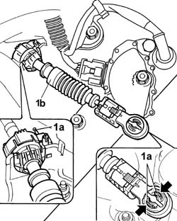
1. Release the retainers (1a) and disconnect the gearbox bowden cable (1b).
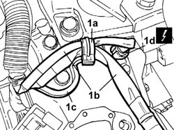
1. Open the band (1a) and release the wiring on the gearbox bowden mounting bracket, then disconnect the gearbox input speed sensor connector (1d).
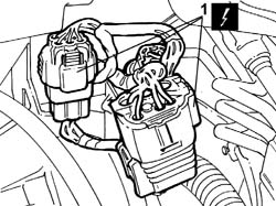
1. Open the retaining band and disconnect the three gearbox main wiring connectors
| Description | Connector | |
|---|---|---|
| 1 | Automatic transmission solenoid valves | L050A |
| Description | Connector | |
|---|---|---|
| 1 | Automatic transmission solenoid valves | L050B |
| Description | Connector | |
|---|---|---|
| 1 | Automatic transmission solenoid valves | L050C |
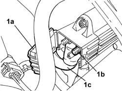
1. Open the flap (1a), undo the nut (1b) fixing the starter motor supply lead (1c) to the junction node and move the lead between the junction node and the motor aside.
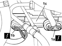
1. Disconnect the connectors (1a) and (1b) for the braking system check control unit (1c) and remove the actual control unit.
| Description | Connector | |
|---|---|---|
| 1a | Braking system check control unit (NBA brake assistance) | M052 |
| Description | Connector | |
|---|---|---|
| 1b | Braking system check control unit (NBA brake assistance) | M052 |
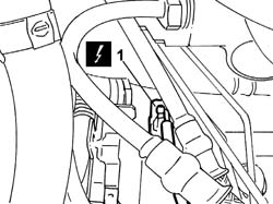
1. Disconnect the gearbox output speed sensor connector.
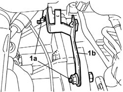
1. Undo the two fixing nuts (1a) and remove the mounting bracket (1b) for the gearbox wiring and the starter motor lead.
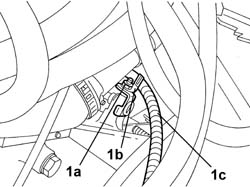
1. Undo the nut (1a) fixing the band (1b) retaining the bowden cable (1c) to the gearbox casing.
- Raise the vehicle
See in Op. 7055B54 PROTECTION/GUARD under engine - R.R.
See in Op. 1080B62 CATALYTIC CONVERTER - R.R.
See in Op. 1076A48 Catalytic converter HEAT SHIELD - R.R.
1. Undo the nut fixing the bowden cable mounting bracket to the bodyshell
2. Carefully open the lower lever support cover spring.
3. Release the bowden cable retainer (3b) and disconnect the end (3a) from the lever support.
4. Remove the bowden cable retainer and release the cable via the lower part of the vehicle.
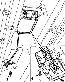
Refitting
- Lower the vehicle
- Position the bowden cable starting from the engine compartment and securing the end to the gear selector.
- Raise the vehicle
- Connect the end of the bowden cable to the idler on the lever support
- Close the lower lever support cover, making sure that all the retaining springs are correctly attached
- Tighten the nut fixing the bowden cable mounting bracket to the bodyshell to the recommended torque.
| Value - daNm | Fastening | Component | Ø | |
|---|---|---|---|---|
| 0.6 | Nut | NUT FIXING BOWDEN MOUNTING BRACKET TO BODYSHELL | M6 |
See in Op. 1076A48 Catalytic converter HEAT SHIELD - R.R.
See in Op. 1080B62 CATALYTIC CONVERTER - R.R.
- Lower the vehicle
- Tighten the nut fixing the bowden cable retaining band to the gearbox casing.
| Value - daNm | Fastening | Component | Ø | |
|---|---|---|---|---|
| 1.7 | Nut | BOWDEN RETAINING BAND TO GEARBOX CASING FIXING, NUT | M6 |
- Position the mounting bracket for the gearbox wiring and the starter motor lead and tighten the two fixing nuts.
- Connect the connector for the gearbox output speed sensor
- Position the braking system check control unit and connect the control unit connectors.
| Description | Connector | |
|---|---|---|
| Braking system check control unit (NBA brake assistance) | M052 |
| Description | Connector | |
|---|---|---|
| Braking system check control unit (NBA brake assistance) | M052 |
- Position the cable between the junction node and the starter motor, then tighten the nut fixing it to the junction node.
- Connect the automatic transmission electrical connectors, then close the band.
| Description | Connector | |
|---|---|---|
| Automatic transmission solenoid valves | L050A |
| Description | Connector | |
|---|---|---|
| Automatic transmission solenoid valves | L050B |
| Description | Connector | |
|---|---|---|
| Automatic transmission solenoid valves | L050C |
- Connect the gearbox output speed sensor connector, then close the band and secure the wiring to the gearbox bowden cable mounting bracket.
- Position the gearbox bowden cable and secure the ends using the retainers.
See in Op. 1048A11 COMPLETE AIR FILTER -R.R.
See in Op. 1016A42 LEFT CYLINDER HEAD IGNITION COIL COVER - R.R.
See in Op. 1048A28 vacuum air circuit resonator pipe - r+r
See in Op. 1048A21 AIR INLET HOSE FROM INTAKE TO FILTER - R.R.
- Connect the negative battery lead, then close the boot.
- Remove the vehicle from the lift.
See in Op. 7040D50 ENGINE COMPARTMENT UPPER SOUND INSULATION SHIELD - R.R.
Removing
- Position the vehicle on a lift.
- Open the boot, remove the cover on the left hand side and disconnect the negative battery lead.
See in Op. 7040D50 ENGINE COMPARTMENT UPPER SOUND INSULATION SHIELD - R.R.
See in Op. 7040L37 GEAR LEVER SURROUNDING TRIM - R.R.
See in Op. 1016A40 Ignition COIL COVER on cylinder head - R.R.
See in Op. 1048A21 AIR INLET HOSE FROM INTAKE TO FILTER - R.R.
See in Op. 1048A28 vacuum air circuit resonator pipe - r+r
1. Release the retainers (1a) and disconnect the gearbox bowden cable (1b).
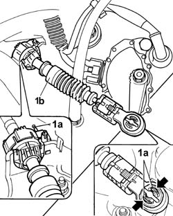
- Raise the vehicle
See in Op. 7055B54 PROTECTION/GUARD under engine - R.R.
1. Undo the bolts fixing the centre section of the exhaust pipe to the intermediate section.
2. Undo the bolt fixing the collar joining the centre section of the exhaust pipe to the rear section.
3. Remove the reinforcement brackets (3a) acting on the fixing bolts (3b).
4. Release the flexible mounting supporting the rear section of the exhaust pipe.
5. Remove the centre section of the exhaust pipe turning it slightly in order to release it from the retaining pin on the rear section of the exhaust pipe.
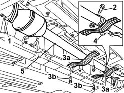
1. Remove the reinforcement bracket (1a) acting on the nuts (1b).
2. Undo the bolts (2a) and remove the heat shields (2b) and (2c) for the centre section of the exhaust pipe.
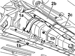
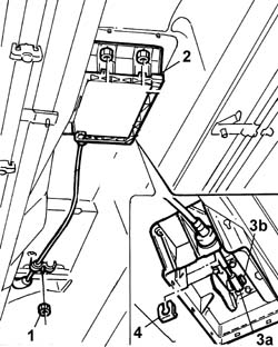
1. Undo the nut fixing the bowden cable mounting bracket to the bodyshell
2. Carefully open the lower lever support cover spring.
3. Release the bowden cable retainer (3b) and disconnect the end (3a) from the lever support.
4. Remove the bowden cable retainer and release the cable via the lower part of the vehicle.
Refitting
- Lower the vehicle
- Position the bowden cable starting from the engine compartment and securing the end to the gear selector.
- Raise the vehicle
- Connect the end of the bowden cable to the idler on the lever support
- Close the lower lever support cover, making sure that all the retaining springs are correctly attached
- Tighten the nut fixing the bowden cable mounting bracket to the bodyshell to the recommended torque.
| Value - daNm | Fastening | Component | Ø | |
|---|---|---|---|---|
| 0.6 | Nut | NUT FIXING BOWDEN MOUNTING BRACKET TO BODYSHELL | M6 |
- Position the heat shields for the centre section of the exhaust pipe and secure them using the bolts.
- Position the reinforcement bracket and secure it using the nuts.
- Position the centre section of the exhaust pipe fitting the pin on the rear section with the reference on the centre section.
- Tighten the bolt fixing the collar joining the centre section of the exhaust pipe to the rear section.
| Value - daNm | Fastening | Component | Ø | |
|---|---|---|---|---|
| (rear section collar) 4.5 | Bolt | INTERMEDIATE EXHAUST PIPE | M10 X 1.25 |
- Secure the rear section of the exhaust pipe to the flexible retaining mounting.
- Tighten the bolts fixing the centre section of the exhaust pipe to the intermediate section.
- Position the reinforcement brackets and secure them using the fixing bolts.
See in Op. 7055B54 PROTECTION/GUARD under engine - R.R.
- Lower the vehicle
- Position the gearbox bowden cable and secure the ends using the retainers.
See in Op. 1048A28 vacuum air circuit resonator pipe - r+r
See in Op. 1048A21 AIR INLET HOSE FROM INTAKE TO FILTER - R.R.
See in Op. 1016A40 Ignition COIL COVER on cylinder head - R.R.
See in Op. 7040L37 GEAR LEVER SURROUNDING TRIM - R.R.
- Connect the negative battery lead, then close the boot.
- Remove the vehicle from the lift.
See in Op. 7040D50 ENGINE COMPARTMENT UPPER SOUND INSULATION SHIELD - R.R.
Parts & tools for this job For 2002 Lancia Thesis
- PARTTransmission filter kitSearch: Lancia Thesis 2002 transmission filter kit
- FLUIDAutomatic transmission fluidSearch: Lancia automatic transmission fluid
- TOOLFluid transfer pumpSearch: fluid transfer pump
Links open Amazon search results in a new tab. As an Amazon Associate I earn from qualifying purchases.