
Power steering - r.r.
- Make
- Lancia
- Model
- Thesis Factory Service Manual
- Year
- 2002–2009
- Section
- Power assisted steering › Power steering - r.r.
POWER STEERING - R.R.
Removing
See in Op. 4130B20 POWER ASSISTED STEERING PUMP - R.R.
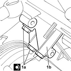
1. Undo the three fixing bolts (1a) and remove the support (1b).
Refitting
- Position the support and tighten the fixing bolts to the recommended torque.
| Value - daNm | Fastening | Component | Ø | |
|---|---|---|---|---|
| 2,5 | Bolt | POWER STEERING PUMP SUPPORT/BRACKET | M8 |
See in Op. 4130B20 POWER ASSISTED STEERING PUMP - R.R.
Removing
- Position the vehicle on a lift.
- Open the boot, remove the cover on the left hand side and disconnect the negative battery lead.
- Raise the vehicle on the lift.
See in Op. 7055B54 PROTECTION/GUARD under engine - R.R.
- Position a suitable container for collecting the engine coolant.
1. Disconnect the lower radiator pipe.
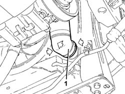
- Working on the band securing the flexible section of the duplex pipe to the rigid section of the supply pipe from the reservoir, drain the power assisted steering system fluid into a suitable container.
- Then restore the connection for the two pipes using a new band.
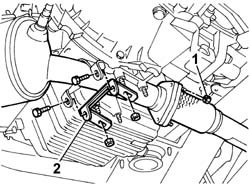
1. Undo the nuts fixing the catalytic converter to the centre section of the exhaust pipe.
2. Remove the mounting bracket for the front section of the exhaust pipe.
See in Op. 4450B04 Right FRONT WHEEL (one) - R.R.
See in Op. 7055B42 FRONT WHEEL ARCH LINER (one), left or right - R.R.
See in Op. 7055B64 Engine compartment DUST SEAL in front wheel arch (one), left or right - R.R.
See in Op. 1048A28 vacuum air circuit resonator pipe - r+r
See in Op. 1048A21 Cold AIR INTAKE PIPE for air filter - R.R.
See in Op. 1048A10 AIR FILTER CASING - R.R.
See in Op. 1016A40 Ignition COIL COVER on cylinder head - R.R.
See in Op. 1076B50 Exhaust PIPE attachment to engine/manifold - R.R.
See in Op. 4450B04 Right FRONT WHEEL (one) - R.R.
See in Op. 7055B42 FRONT WHEEL ARCH LINER (one), left or right - R.R.
See in Op. 7055B64 Engine compartment DUST SEAL in front wheel arch (one), left or right - R.R.
See in Op. 1048A21 Cold AIR INTAKE PIPE for air filter - R.R.
See in Op. 1048A10 AIR FILTER CASING - R.R.
See in Op. 1016A10 SOUND-PROOFING COVER - R.R.
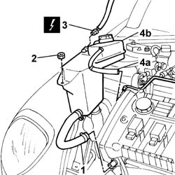
1. Disconnect the coolant pipe retaining band on the cylinder head.
2. Undo the nut fixing the expansion tank (this nut also fastens the windscreen washer fluid reservoir).
3. Disconnect the electrical connection for the engine coolant level.
| Description | Connector | |
|---|---|---|
| 3 | Engine coolant level sensor | K026 |
4. Disconnect the pipe (4a) and lift up the expansion tank (4b) and remove it.
1. Undo the bolt fixing the engine oil dipstick pipe.
2. Undo the bolt (2a), loosen the bolt (2b) and rotate the reaction rod connecting rod.
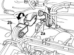
1. Undo the bolt (1a), open the retaining brackets (1b) and remove the engine coolant recovery pipe (1c).
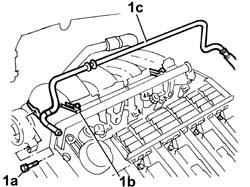
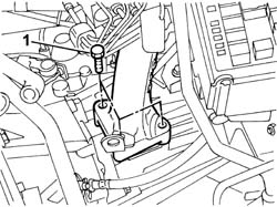
- Position a hydraulic lift under the gearbox bellhousing.
1. Undo the bolts fixing the engine support to the gearbox.
- Gradually lower the hydraulic lift and rest the gearbox on the front crossmember.
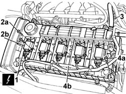
1. Disconnect the electrical connections from the ignition coils.
| Description | Connector | |
|---|---|---|
| 1 | Ignition coil | A030A |
| Description | Connector | |
|---|---|---|
| 1 | Ignition coil | A030B |
| Description | Connector | |
|---|---|---|
| 1 | Ignition coil | A030C |
| Description | Connector | |
|---|---|---|
| 1 | Ignition coil | A030D |
| Description | Connector | |
|---|---|---|
| 1 | Ignition coil | A030E |
2. Undo the bolts (2a) and remove the ignition coils (2b).
3. Disconnect the oil vapour recovery pipes.
4. Undo the bolts (4a) and remove the tappet cover (4b) complete with gasket.
See in Op. 1092G10 Engine components single drive BELT - R.R.
See in Op. 1092A10 Auxiliary shaft pulley - R.R.
See in Op. 1032B10 TOOTHED timing BELT - R.R. for timing adjustment or replacement
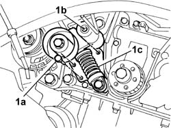
1. Undo the three bolts (1a) and the hexagonal bolt (1b) and remove the automatic tensioning device (1c) for the auxiliary shaft drive belt.
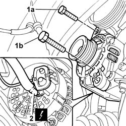
1. Undo the upper bolt (1a) and the lower bolt (1b) fixing the alternator.
2. Disconnect the electrical connections from the alternator and remove it.
| Description | Connector | |
|---|---|---|
| 2 | Alternator | A010A |
| Description | Connector | |
|---|---|---|
| 2 | Alternator | A010B |
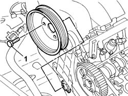
1. Undo the bolts fixing the power assisted steering pump pulley (to faciliate this operation, loosen the bolts before removing the auxiliary shaft drive belt).
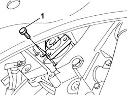
1. Undo the four bolts fixing the power assisted steering pump to the mounting; move the pump away from the mounting without disconnecting the pipes connected to it.
1. Undo the bolt fixing the power assisted steering fluid supply pipe mounting bracket to the steering box.
2. Undo the lower bolts fixing the power assisted steering pump mounting bracket.
3. Undo the nut (3a) fixing the moving tensioner and the bolt (3b) fixing the timing drive belt fixed tensioner.
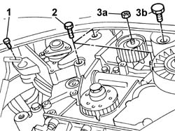
- Lower the vehicle on the lift.
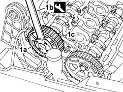
1. Undo the bolts (1a) using the tool (1b) for counter-torque and remove the inlet side camshaft drive pulley (1c).
| Description | Code | Function | |
|---|---|---|---|
| 1b | Counter-torque | 1.860.856.000 | Loosen/tighten inlet side camshaft drive pulley |
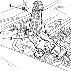
1. Undo the upper bolt fixing the power assisted steering pump mounting.
2. Remove the power assisted steering pump mounting upwards taking care not to damage the bodywork.
Refitting
- Position the power assisted steering pump mounting bracket taking care not to damage the bodywork.
- Tighten the bolts fixing the power assisted steering pump support to the recommended torque.
| Value - daNm | Fastening | Component | Ø | |
|---|---|---|---|---|
| 5 | Bolt | THERMOSTATIC POWER ASSISTED STEERING PUMP MOUNTING/BRACKETS | M10 X 1.25 |
- Position the inlet side camshaft drive pulley and tighten the fixing bolts using the special tool for counter-torque.
| Description | Code | Function | |
|---|---|---|---|
| Counter-torque | 1.860.856.000 | Loosen/tighten inlet side camshaft drive pulley |
| Value - daNm | Fastening | Component | Ø | |
|---|---|---|---|---|
| (inlet side) 0.9 | Bolt | TIMING DRIVEN PULLIES | M6 |
- Position the moving tensioner for the timing drive belt and tighten the fixing nut.
- Position the fixed timing belt tensioner and tighten the retaining bolt to torque.
| Value - daNm | Fastening | Component | Ø | |
|---|---|---|---|---|
| 5 | Bolt | FIXED TENSIONER | M10 X 1.25 |
- Fasten the bolt fixing the power assisted steering fluid supply pipe mounting bracket to the steering box.
- Place the power assisted steering pump in position and fasten it to the mounting using the fixing bolts.
| Value - daNm | Fastening | Component | Ø | |
|---|---|---|---|---|
| 2.5 | Bolt | POWER STEERING PUMP | M8 |
- Position the power assisted steering pump drive pulley and secure it using the bolts.
- Position the alternator and fasten it using the bolts.
| Value - daNm | Fastening | Component | Ø | |
|---|---|---|---|---|
| 5 | Nut | ALTERNATOR ASSEMBLY | M10 X 1.25 |
| Value - daNm | Fastening | Component | Ø | |
|---|---|---|---|---|
| 7 | Nut | ALTERNATOR ASSEMBLY | M12 X 1.25 |
- Connect the electrical connections to the alternator.
| Description | Connector | |
|---|---|---|
| Alternator | A010A |
| Description | Connector | |
|---|---|---|
| Alternator | A010B |
- Position the auxiliary drive belt automatic tensioner.
| Value - daNm | Fastening | Component | Ø | |
|---|---|---|---|---|
| 5 | Bolt | SINGLE BELT MOVING TENSIONER VARIOUS | M10 X 1.25 |
| Value - daNm | Fastening | Component | Ø | |
|---|---|---|---|---|
| 2.5 | Bolts | SINGLE BELT MOVING TENSIONER VARIOUS | M8 |
See in Op. 1032B10 TOOTHED timing BELT - R.R. for timing adjustment or replacement
See in Op. 1092A10 Auxiliary shaft pulley - R.R.
See in Op. 1092G10 Engine components single drive BELT - R.R.
- Position a hydraulic lift under the gearbox bellhousing.
- Screw in and tighten the bolt fixing the engine support to the gearbox to the recommended torque.
| Value - daNm | Fastening | Component | Ø | |
|---|---|---|---|---|
| (on gearbox) 5 | Bolt | POWER UNIT GEAR BOX END RIGID MOUNT | M10 X 1.25 |
- Raise the vehicle on the lift.
- Tighten the nuts fixing the catalytic converter to the centre section of the exhaust pipe.
| Value - daNm | Fastening | Component | Ø | |
|---|---|---|---|---|
| (to cable centre section) 2.8 | Nut | CATALYTIC CONVERTER (ONE) | M8 |
- Fit the mounting bracket for the front section of the exhaust pipe.
| Value - daNm | Fastening | Component | Ø | |
|---|---|---|---|---|
| (on engine oil sump) 4 | Nut | CATALYTIC CONVERTER MOUNT | M10 X 1.25 |
| Value - daNm | Fastening | Component | Ø | |
|---|---|---|---|---|
| (to catalytic converter) 2.8 | Bolt | CATALYTIC CONVERTER MOUNT | M8 |
- Position the tappet cover and secure it using the fixing bolts.
| Value - daNm | Fastening | Component | Ø | |
|---|---|---|---|---|
| 0.9 | Bolt | CAM COVER | M6 |
- Position the ignition coils cover and secure them using the fixing bolts.
| Value - daNm | Fastening | Component | Ø | |
|---|---|---|---|---|
| 0.9 | Bolt | IGNITION COIL/REEL | M6 |
- Connect the electrical connections for the ignition coils, then reposition the wiring on the tappet cover retaining brackets.
| Description | Connector | |
|---|---|---|
| Ignition coil | A030A |
| Description | Connector | |
|---|---|---|
| Ignition coil | A030B |
| Description | Connector | |
|---|---|---|
| Ignition coil | A030C |
| Description | Connector | |
|---|---|---|
| Ignition coil | A030D |
| Description | Connector | |
|---|---|---|
| Ignition coil | A030E |
- Connect the oil vapour recovery pipes to the tappet cover.
- Position the coolant recovery pipe.
See in Op. 1076B50 Exhaust PIPE attachment to engine/manifold - R.R.
- Connect the connecting rod to the reaction rod and secure it using the bolts.
| Value - daNm | Fastening | Component | Ø | |
|---|---|---|---|---|
| (to bracket on bodyshell) 5 | Bolt | POWER UNIT REACTION ROD | M10 X 1.25 |
| Value - daNm | Fastening | Component | Ø | |
|---|---|---|---|---|
| (to engine support) 5 | Bolt | POWER UNIT REACTION ROD | M10 X 1.25 |
- Tighten the bolt fixing the engine oil dipstick pipe.
- Position the expansion tank and secure it using the nut.
- Connect the pipes and the electrical connection for the engine coolant level.
| Description | Connector | |
|---|---|---|
| Engine coolant level sensor | K026 |
See in Op. 1048A10 COMPLETE AIR FILTER -R.R.
See in Op. 1048A21 AIR INLET HOSE FROM INTAKE TO FILTER - R.R.
See in Op. 1048A28 vacuum air circuit resonator pipe - r+r
See in Op. 1016A40 Ignition COIL COVER on cylinder head - R.R.
See in Op. 7055B64 Engine compartment DUST SEAL in front wheel arch (one), left or right - R.R.
See in Op. 7055B42 FRONT WHEEL ARCH LINER (one), left or right - R.R.
See in Op. 4450B04 Right FRONT WHEEL (one) - R.R.
- Connect the negative battery lead, then close the boot.
See in Op. 0010T20 Engine REFRIGERANT FLUID - Change
See in Op. 7055B54 PROTECTION/GUARD under engine - R.R.
- Remove the vehicle from the lift.
See in Op. 1016A10 SOUND-PROOFING COVER - R.R.
See in Op. 1048A10 AIR FILTER CASING - R.R.
See in Op. 1048A21 Cold AIR INTAKE PIPE for air filter - R.R.
See in Op. 7055B64 Engine compartment DUST SEAL in front wheel arch (one), left or right - R.R.
See in Op. 7055B42 FRONT WHEEL ARCH LINER (one), left or right - R.R.
See in Op. 4450B04 Right FRONT WHEEL (one) - R.R.
- Refill the power assisted steering system using the appropriate fluid.
| Description | Qty. | Component | Type | Classification | |
|---|---|---|---|---|---|
| TUTELA HP 20 | POWER ASSISTED STEERING CIRCUIT | Oil | ATF DEXRON III |
- Continue with the bleeding procedure following the instructions given below.
- With the front wheels raised off the ground and the engine switched off, carry out 4 or 5 complete rotations of the steering wheel (left and right).
- Check and, if necessary, top up the power assisted steering fluid level.
- Position the vehicle on the ground and start up the engine.
- Carry out 4 or 5 complete rotations of the steering wheel (left and right).
- If necessary, top up the power assisted steering fluid level.
- Connect the negative battery lead, then close the boot.
See in Op. 0010T20 Engine REFRIGERANT FLUID - Change
See in Op. 7055B54 PROTECTION/GUARD under engine - R.R.
- Remove the vehicle from the lift.
Removing
- Position the vehicle on a lift.
- Open the boot, remove the cover on the left hand side and disconnect the negative battery lead.
See in Op. 7055B54 PROTECTION/GUARD under engine - R.R.
See in Op. 4450B04 Right FRONT WHEEL (one) - R.R.
See in Op. 7055B42 FRONT WHEEL ARCH LINER (one), left or right - R.R.
See in Op. 7055B64 Engine compartment DUST SEAL in front wheel arch (one), left or right - R.R.
See in Op. 1016A10 SOUND-PROOFING COVER - R.R.
See in Op. 7040D50 ENGINE COMPARTMENT UPPER SOUND INSULATION SHIELD - R.R.
See in Op. 1048B44 RIGID air supply PIPE from heat exchanger to intake manifold - R.R.
See in Op. 1048A56 UPPER RESONATOR - R.R.
See in Op. 1092G10 Engine components single drive BELT - R.R.
See in Op. 1092G21 Engine components single belt FIXED TENSIONER - R.R. with belt removed
See in Op. 1092A10 Crankshaft PULLEY - R.R.
See in Op. 1032D12 Timing system protective COVER(S) - R.R.
See in Op. 1032B10 TOOTHED timing BELT - R.R. for timing adjustment or replacement
See in Op. 1092G40 Engine components single belt cam TENSIONER - R.R.
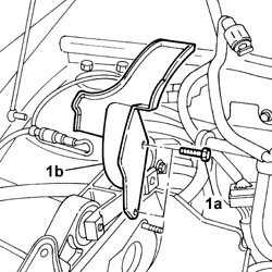
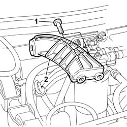
1. Undo the two retaining bolts (1a) and remove the power assisted steering pump guard (1b).
1. Undo the fixing bolts.
2. Remove the alternator rear mounting bracket.
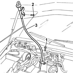
1. Undo the lower bolt securing the engine oil dipstick tube.
- Lower the lift.
2. Undo the upper bolt securing the engine oil dipstick tube.
3. Release the coupling for the engine wiring from the fastening on the pipe, then remove the engine oil dipsick pipe from the upper part of the engine compartment.
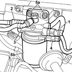
1. Disconnect the front supply pipe from the fuel filter.
2. Disconnect the supply pipe to the pressure pump from the fuel filter.
3. Disconnect the supply pipe to the fuel return manifold from the fuel filter.
4. Disconnect the electrical connections for the diesel heater resistances.
| Description | Connector | |
|---|---|---|
| 4 | Diesel pre-heating resistance | O020A |
| Description | Connector | |
|---|---|---|
| 4 | Diesel pre-heating resistance | O020B |
- Disconnect the electrical connection for the water presence sensor.
| Description | Connector | |
|---|---|---|
| Water in diesel filter sensor | K031 |
5. Undo the fixing nuts (5a) and remove the fuel filter assembly (5b).
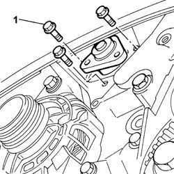
1. Undo the bolts fixing the power assisted steering pump and move it from its housing retracting it.
- Open the protective cover and disconnect the alternator electrical connections.
| Description | Connector | |
|---|---|---|
| Alternator | A010A |
| Description | Connector | |
|---|---|---|
| Alternator | A010B |
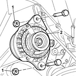
1. Undo the upper bolts and the lower bolts fixing the alternator to the mounting.
2. Remove the alternator from the housing on the mounting.
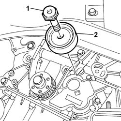
1. Undo the retaining bolt.
2. Remove the timing belt fixed tensioner.
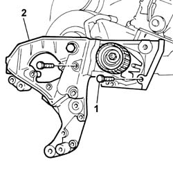
- Undo the bolt fixing the side plastic shield for the timing belt t the power assisted steering pump support.
1. Undo the bolts fixing the power assisted steering pump mounting.
2. Remove the power assisted steering pump mounting taking care not to damage the bodywork.
Refitting
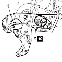
1. Posiion the power assisted steering pump mounting taking care not to damage the bodywork.
2. Tighten the bolts fixing the power assisted steering pump support to the recommended torque.
| Value - daNm | Fastening | Component | Ø | |
|---|---|---|---|---|
| 2 | 5 | Bolt | THERMOSTATIC POWER ASSISTED STEERING PUMP MOUNTING/BRACKETS | M10 X 1.25 |
1. Position the fixed timing belt tensioner and tighten the retaining bolt to torque.
| Value - daNm | Fastening | Component | Ø | |
|---|---|---|---|---|
| 1 | 5 | Bolt | FIXED TENSIONER | M10 X 1.25 |
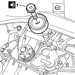
- Tighten the bolt fixing the side plastic shield for the timing belt t the power assisted steering pump support.
- Position the alternator in its housing and fasten it using the fixing bolts.
| Value - daNm | Fastening | Component | Ø | |
|---|---|---|---|---|
| 5 | Nut | ALTERNATOR ASSEMBLY | M10 X 1.25 |
| Value - daNm | Fastening | Component | Ø | |
|---|---|---|---|---|
| 7 | Nut | ALTERNATOR ASSEMBLY | M12 X 1.25 |
- Connect the electrical connections to the alternator.
| Description | Connector | |
|---|---|---|
| Alternator | A010A |
| Description | Connector | |
|---|---|---|
| Alternator | A010B |
1. Place the power assisted steering pump in position and fasten it to the mounting using the fixing bolts.
| Value - daNm | Fastening | Component | Ø | |
|---|---|---|---|---|
| 1 | 2.5 | Bolt | POWER STEERING PUMP | M8 |
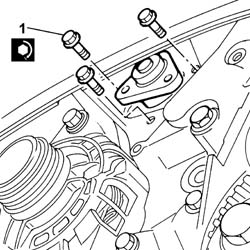
- Fit the fuel filter assembly and tighten the fixing nuts to torque.
| Value - daNm | Fastening | Component | Ø | |
|---|---|---|---|---|
| 2.4 | Nut | FUEL FILTER | M8 |
- Connect the electrical connections for the sensors.
| Description | Connector | |
|---|---|---|
| Water in diesel filter sensor | K031 |
| Description | Connector | |
|---|---|---|
| Diesel pre-heating resistance | O020A |
| Description | Connector | |
|---|---|---|
| Diesel pre-heating resistance | O020B |
- Connect the fuel pipes disconnected previously.
- Fit the engine oil dipstick pipe via the top of the engine compartment.
- Secure the engine cables coupling to the engine oil dipstick pipe.
- Raise the vehicle.
- Tighten the lower bolt securing the engine oil dipstick tube.
- Fit the alternator rer mounting bracket and tighten the fixing bolts.
- Fit the power assisted steering pump guard and tighten the retaining bolts.
See in Op. 1092G40 Engine components single belt cam TENSIONER - R.R.
See in Op. 1032B10 TOOTHED timing BELT - R.R. for timing adjustment or replacement
See in Op. 1032D12 Timing system protective COVER(S) - R.R.
See in Op. 1092A10 Crankshaft PULLEY - R.R.
See in Op. 1092G21 Engine components single belt FIXED TENSIONER - R.R. with belt removed
See in Op. 1092G10 Engine components single drive BELT - R.R.
See in Op. 1048A56 UPPER RESONATOR - R.R.
See in Op. 1048B44 RIGID air supply PIPE from heat exchanger to intake manifold - R.R.
See in Op. 7040D50 ENGINE COMPARTMENT UPPER SOUND INSULATION SHIELD - R.R.
See in Op. 1016A10 SOUND-PROOFING COVER - R.R.
See in Op. 7055B64 Engine compartment DUST SEAL in front wheel arch (one), left or right - R.R.
See in Op. 7055B42 FRONT WHEEL ARCH LINER (one), left or right - R.R.
See in Op. 4450B04 Right FRONT WHEEL (one) - R.R.
See in Op. 7055B54 PROTECTION/GUARD under engine - R.R.
- Open the boot, connect the negative battery lead and fit the cover on the battery.
- Remove the vehicle from the lift.
Parts & tools for this job For 2002 Lancia Thesis
- TOOLTie rod end toolSearch: tie rod end puller
- TOOLBall joint separatorSearch: ball joint separator
- FLUIDPower steering fluidSearch: Lancia power steering fluid
Links open Amazon search results in a new tab. As an Amazon Associate I earn from qualifying purchases.