
Multi-function components
- Make
- Lancia
- Model
- Ypsilon Factory Service Manual
- Year
- 2003–2011
- Section
- Electrical circuit for instruments/indicators › Multi-function components
Multi-function components
Specifications
The driver's door node is located inside the driver's door panel, as illustrated in the diagram.
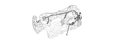
1 - Door Node
Specifications
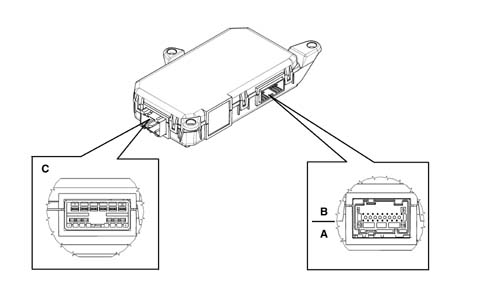
The control unit performs the following functions:
- door lock/release;
- outdoor temperature signal
- door status led
Specifications
Connector C pinout:
| Pin | Operation |
|---|---|
| relay | Electronic earth |
| relay | N.C. |
| 3 | Driver's side deadlock gear motor (N.C.) |
| 4 | Driver's lock motors |
| 5 | Driver's locking/unlocking geared motor |
| 6 | Fuel flap lock/release gear motor (NC) |
| 7 | Supply direct |
| 8 | Power earth |
| 9 | Passenger side locking/unlocking geared motor |
| 10 | Fuel flap lock/release gear motor (NC) |
| 11. | Passenger side dead lock geared motor (NC) |
| 12. | Passenger side lock motors |
B/A connector pinout
| Pin | Operation |
|---|---|
| relay | Negative signal from switch on d.s. lock |
| relay | Negative signal from switch on d.s. lock |
| 3 | Door release control negative signal from button |
| 4 | Door locking control negative signal from button |
| 5 | Negative signal from switch in p.s. lock |
| 6 | Negative signal from switch in p.s. lock |
| 7 | Negative signal from passenger side motor bar switch (NC) |
| 8 | Negative signal from passenger side N.A. motor switch (lock) |
| 9 | Negative signal from driver's side N.A. motor switch (lock) |
| 10 | Signal from outside temperature sensor |
| 11. | B-CAN B |
| 12. | B-CAN A |
| 13 | Door status LED positive control |
| 14 | Interior handle lighting earth (NC) |
| 15 | Earth for door status LED |
| 16 | Outside temperature sensor earth |
| 17 | Driver's side lock earth |
| 18 | Negative signal from driver's side motor bar switch (NC) |
SPECIFICATIONS
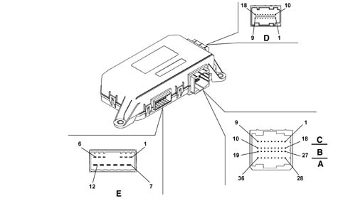
The driver's door node is located inside the driver's door panel
Its functions, listed below, are:
- Management of doors/boot and fuel flap locking / unlocking
- Front electric windows with manual and automatic up/down and anti-crush safety function
- Electric door mirrors
- Demister timer management
- Outdoor temperature acquisition and management
- Door/boot opening
- Friction catches with switch
- Deadlock engagement/release
- Vehicle protection system signals
Driver's door node
SPECIFICATIONS
Connector E
| PIN | OPERATION |
|---|---|
| relay | Door open gear motor (negative) (NC) |
| relay | Door opening geared motor (positive) (NC) |
| 3 | Dead-lock geared motor |
| 4 | Door locking / unlocking geared motor |
| 5 | Fuel flap lock/release gear motor |
| 6 | Lock motor shared |
| 7 | Power earth |
| 8 | Electric window power supply |
| 9 | Window closing positive control |
| 10 | Window opening positive control |
| 11. | NPG node power supply |
| 12. | Fuel flap lock/release gear motor |
C/B/A connector
| PIN | OPERATION |
|---|---|
| relay | not connected |
| relay | Window anti-crush safety sensor (signal) |
| 3 | not connected |
| 4 | Earth for interior handle lighting led (NC) |
| 5 | Window anti-crush sensor (negative) |
| 6 | Earth for door status LED |
| 7 | not connected |
| 8 | Door status LED positive control |
| 9 | Interior handle lighting LED positive control (NC) |
| 10 | not connected |
| 11. | not connected |
| 12. | not connected |
| 13 | not connected |
| 14 | not connected |
| 15 | B-CAN B |
| 16 | B-CAN A |
| 17 | not connected |
| 18 | not connected |
| 19 | Electronic earth |
| 20 | not connected |
| 21 | Negative opening signal from exterior handle switch (NC) |
| 22 | Earth for lock |
| 23 | Negative signal from N.A. motor switch (lock) |
| 24 | Negative signal from switch in lock |
| 25 | Negative signal from switch in lock |
| 26 | not connected |
| 27 | not connected |
| 28 | Analogue signal to control electric rear view mirrors (up/down movement) |
| 29 | Analogue signal to control electric rear view mirrors (left/right movement) |
| 30 | Analogue signal to control electric rear view mirrors selection (driver's side/passenger side) |
| 31 | Analogue signal from front electric window controls d.s. |
| 32 | Analogue signal from front electric window controls passenger side |
| 33 | Switch trim earth |
| 34 | Door locking control signal from button |
| 35 | Door unlocking control signal from button |
| 36 | Switch panel on armrest dimmed light positive control |
Connector D (connection with door mirror)
| PIN | OPERATION |
|---|---|
| relay | not connected |
| relay | Signal from outside temperature sensor |
| 3 | Left/right mirror deflector implementation |
| 4 | Mirror deflector common motors |
| 5 | High/low mirror deflector implementation |
| 6 | Outside temperature sensor negative |
| 7 | Mirror defroster protected supply |
| 8 | not connected |
| 9 | Mirror defroster timed negative control |
| 10 | not connected |
| 11. | not connected |
| 12. | not connected |
| 13 | not connected |
| 14 | not connected |
| 15 | not connected |
| 16 | not connected |
| 17 | not connected |
| 18 | not connected |
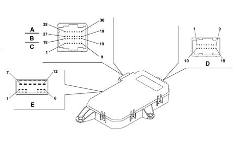
Passenger door node
SPECIFICATIONS
Connector E
| PIN | OPERATION |
|---|---|
| relay | Door opening geared motor (negative) (NC) |
| relay | Door opening geared motor (positive) (NC) |
| 3 | Dead-lock geared motor |
| 4 | Door locking / unlocking geared motor |
| 5 | not connected |
| 6 | Lock motor shared |
| 7 | Power earth |
| 8 | Electric window power supply |
| 9 | Window closing positive control |
| 10 | Window opening positive control |
| 11. | NPP node power supply |
| 12. | not connected |
Connector C/B/A
| PIN | OPERATION |
|---|---|
| relay | not connected |
| relay | Window anti-crush safety sensor (signal) |
| 3 | not connected |
| 4 | Earth for interior handle lighting LED (NC) |
| 5 | Window anti-crush sensor (negative) |
| 6 | not connected |
| 7 | not connected |
| 8 | not connected |
| 9 | Interior handle lighting LED positive control |
| 10 | not connected |
| 11. | not connected |
| 12. | not connected |
| 13 | not connected |
| 14 | not connected |
| 15 | B-CAN B |
| 16 | B-CAN A |
| 17 | not connected |
| 18 | not connected |
| 19 | Electronic earth |
| 20 | Negative signal from N.C. motor bar switch (NC) |
| 21 | Negative opening signal from exterior handle switch (NC) |
| 22 | Earth for lock |
| 23 | Negative signal from N.A. motor switch (lock) |
| 24 | Negative signal from switch in lock |
| 25 | Negative signal from switch in lock |
| 26 | not connected |
| 27 | not connected |
| 28 | not connected |
| 29 | not connected |
| 30 | not connected |
| 31 | not connected. |
| 32 | Analogue signal from front electric window controls passenger side |
| 33 | Switch trim earth |
| 34 | not connected |
| 35 | not connected |
| 36 | Switch panel lighting dimmer positive control |
Connector D (connection with door mirror)
| PIN | OPERATION |
|---|---|
| relay | not connected |
| relay | not connected |
| 3 | Left/right mirror deflector implementation |
| 4 | Mirror deflector common motors |
| 5 | High/low mirror deflector implementation |
| 6 | not connected |
| 7 | Mirror defroster protected supply |
| 8 | not connected |
| 9 | Mirror defroster timed negative control |
| 10 | not connected |
| 11. | not connected |
| 12. | not connected |
| 13 | not connected |
| 14 | not connected |
| 15 | not connected |
| 16 | not connected |
| 17 | not connected |
| 18 | not connected |
Front electric windows with manual and automatic up/down and anti-crush safety function
The NPG receives the electric window commands for both the driver's front door and the passenger front door. It also directly controls its own electric window motor and transmits the commands for the NPP via the CAN.
The NPP only receives commands for the passenger front door and controls its own motor directly.
The motors for the driver's and passenger doors are controlled both manually and automatically, according to the logic:
- the manual mode involves starting and stopping the window manually by the user through the button for a time of: 50 ms < Ta < 300 ms (short control) and when the latter is released, the motor stops;
- the automatic mode involves starting the window manually by the user using the button for a time of: ta > 300 ms (long control).
The node must cut off window operation in the following cases:
- when automatic movement is in progress and either the up or down control is pressed again;
- the window reaching the upper or lower end of its travel in automatic or manual mode
- this is regulated exclusively by checking the motor current;
After a key off the front windows can be operated either manually or automatically for a period of 2 minutes managed by the NPG and NPP. When this period elapses, the node no longer receives new commands, but brings any received before the 2 minute has elapsed to a conclusion;
If, during the timing, both nodes detect the opening of one of the doors, the node no longer receives new commands, but brings those received before the door was opened to a conclusion;
If one of the doors was already open at the key off, the nodes bring any commands received before the door was opened to a conclusion.
Window central closing
This function makes it possible to close all the windows in a single operation.
The central closing function using the remote control or lock catch in the driver's and passenger front door outside handle (signals managed by the NBC) is only activated at the key off.
The central closing of the windows can only be carried out using a specific signal sent to the CAN network by the NBC. This command is received directly by the NPG and NPP which implement the movement of the appropriate windows to closure.
Window central opening
This function makes it possible to open all the windows in a single operation.
The central opening function using the remote control or lock catch in the driver's and passenger front door outside handle (signals managed by the NBC) is only activated at the key off.
The central opening of the windows can only be carried out using a specific signal sent to the CAN network by the NBC. This command is received directly by the NPG and NPP which implement the movement of the appropriate windows to full opening.
Antipinch function
If the antipinch function is activated, the node which manages the movement of the window receives information that the seal is compressed through a resistive sensor fitted in a special casing fitted to the window upper trim.
The sensor is the resistive type.
There are two inputs for each sensor: signal and earth from control unit.
This occurs in both manual and automatic operation.
As a consequence of this event, the node immediately interrupts the travel of the glass and reverses it to the lower buffer position.
The node does not accept any type of command during this period.
If the antipinch safety function intervenes 5 consecutive times within a minute or is faulty, the door nodes inhibit the automatic closing operation only allowing it in steps of 500 ms when the button is released for the next manoeuvre.
In order to be able to restore the correct operation of the system one of the following conditions must be satisfied:
- a key off - key operation
- a downwards movement of the glass in question carried out by the user
Electric external mirrors
The NPG receives the movement commands for both the driver's mirror and the passenger mirror.
The NPG manages the movement of the driver's external mirror directly and transmits the commands for moving the passenger external mirror via the B-CAN.
The NPP receives the commands and manages the passenger external mirror directly.
The NPG receives the adjustment commands for both external rear view mirrors. The commands are produced by a joystick for the adjustments and two separate buttons for the mirror selection (one to select the left mirror and the other for the right mirror).
Timed defrosting management
The defrosting function follows the same logic as the:
- heated rear windscreen (managed directly by the NBC)
- rear view mirrors (left, right) managed by the door nodes (NPG and NPP)
The implementation of the mirror defrosting, heated rear windscreen and jets is activated by:
- command from the button on the heater/climate control which is received by the NBC.
- demist command from the Max Defrost function.
The operation of the mirror defrosting, heated rear windscreen and windscreen washer juets coming from the Max Defrost function follows the same logic as the specific control on the heater / climate control.
Timing logic
The activation of the defrosting function lasts a maximum of 20 minutes at the end of which it is switched off.
The defrosting activation / deactivation logic is as follows:
- for the first 15 minutes operation does not depend on the engine speed.
- afterwards the operation depends on the engine conditions, namely if the engine speed is below 960 rpm for 10 seconds, the defrosting function is deactivated, if the engine speed is above 1056 rpm for 5 seconds, the defrosting function is activated once again.
The automatic activation cycle (20 minutes) is reset upon each activation COMMAND through the dedicated button.
Throughout the operating cycle, if battery voltage drops below 8.5V, the defrosting relays go off.
Outside temperature management
The NPG receives the outside temperature information through the specific NTC sensor located under the left external rear view mirror and periodically transmits this value through the B - CAN network.
Depending on the outside temperature, the panel displays the outside temperature value and warn the user of the possibility of ice through a symbol and specific message.
On versions with automatic climate control, the Climate Control Node receives the outside temperature value from the B - CAN network for the management of the passenger compartment climate control.
Lock lock/release command
See description under Characteristic of working principle 5580E anti-theft device
Parts & tools for this job For 2003 Lancia Ypsilon
- TOOLDigital multimeterSearch: automotive digital multimeter
- PARTAssorted fuse kitSearch: car fuse assortment kit
- TOOLWire crimper and connector kitSearch: wire crimper connector kit
Links open Amazon search results in a new tab. As an Amazon Associate I earn from qualifying purchases.