
Fuel delivery line - r r
- Make
- Lancia
- Model
- Ypsilon Factory Service Manual
- Year
- 2003–2011
- Section
- Fuel tank and pipes › Fuel delivery line - r r
Fuel delivery line - r r
Removing
Position the vehicle on the ramp.
Ensure that the ignition key is in OFF position, then disconnect the battery negative terminal (-).
| Name | Connector | |
|---|---|---|
| Battery | A1B |
Proceed with removal - 1048A10 air cleaner filtering element - replace.
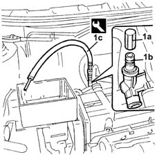
1. Remove the protective cap (1a) for the breather valve on fuel manifold (1b) and use the tool (1c) to discharge the fuel pressure in the fuel circuit.
Recover the fuel which comes out in a suitable container.
| Name | Country | |
|---|---|---|
| 1c | Rapid connector | 1.870.684.000 |
Removing
Position the vehicle on the ramp.
Ensure that the ignition key is in OFF position, then disconnect the battery negative terminal (-).
| Name | Connector | |
|---|---|---|
| Battery | A1B |
Proceed with removal - 1048A10 air cleaner filtering element - replace.
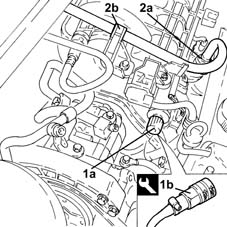
1. Remove the protective cap (1a) for the fuel manifold (1b) and use the tool (1c) to discharge the fuel pressure in the fuel circuit.
Recover the fuel which comes out in a suitable container.
| Name | Country | |
|---|---|---|
| 1b | Rapid connector | 1.870.684.000 |
2. Disconnect the rapid connector for the fuel delivery pipe (2a) from the fuel manifold pipe and release from its fastenings (1b).
Removing
Position the vehicle on the ramp.
Ensure that the ignition key is in OFF position, then disconnect the battery negative terminal (-).
| Name | Connector | |
|---|---|---|
| Battery | A1B |
Proceed with removal - 1048A10 air cleaner filtering element - replace.
1. Remove the protective cap (1a) for the fuel manifold (1b) and use the tool (1c) to discharge the fuel pressure in the fuel circuit.
Recover the fuel which comes out in a suitable container.
| Name | Country | |
|---|---|---|
| 1b | Rapid connector | 1.870.684.000 |
2. Disconnect the rapid connector for the fuel delivery pipe (2a) from the fuel manifold pipe and release from its fastenings (1b).
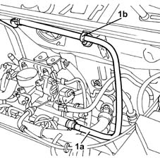
1. Disconnect the rapid connector for the fuel delivery pipe (1a), fuel manifold pipe side and release from its fastenings (1b).
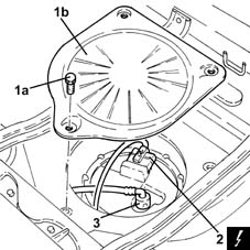
Lift the rear seat cushion lift the floor covering to gain access to the submerged fuel assembly.
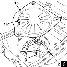
1. Undo the bolts (1a) and remove the protective cover (1b).
2. Disconnect the electrical connection from the fuel pump and level gauge.
| Name | Connector | |
|---|---|---|
| 2 | Fuel pump and sender unit | N40 |
3. Disconnect the rapid attachment for the fuel supply pipe.
Lift the rear seat cushion lift the floor covering to gain access to the submerged fuel assembly.
1. Undo the bolts (1a) and remove the protective cover (1b).
2. Disconnect the electrical connection from the fuel pump and level gauge.
| Name | Connector | |
|---|---|---|
| 2 | Fuel pump and sender unit | N40 |
3. Disconnect the rapid attachment for the fuel supply pipe.
Lift the rear seat cushion lift the floor covering to gain access to the submerged fuel pump assembly.
1. Undo the bolts (1a) and remove the protective cover (1b).
2. Disconnect the electrical connection from the fuel pump and level gauge.
| Name | Connector | |
|---|---|---|
| 2 | Fuel pump and sender unit | N40 |
3. Disconnect the rapid attachment for the fuel supply pipe.
Proceed with removal - 4450B04 right front wheel r r.
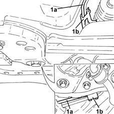
1. Release fuel delivery pipe (1a) from fastenings (1b) on the front suspension beam.
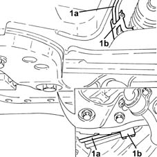
Proceed with removal - 4450B04 right front wheel r r.
1. Release fuel delivery pipe (1a) from fastenings (1b) on the front suspension beam.
Proceed with removal - 4450B04 right front wheel r r.
1. Release fuel delivery pipe (1a) from fastenings (1b) on the front suspension beam.
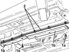
1. Undo bolts (1a) and remove protection (1b).
2. Release the fuel supply pipe from the fixings under the body.
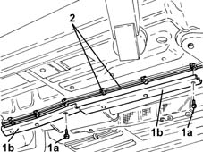
1. Undo bolts (1a) and remove protection (1b).
2. Release the fuel supply pipe from the fixings under the body.
1. Undo bolts (1a) and remove protections (1b).
2. Release the fuel supply pipe from the fixings under the body.
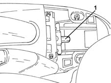
Proceed with removal - 7040L22 REAR TRIM on TUNNEL -R.R..
1. Slacken the handbrake cable adjustment nut.
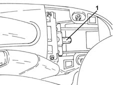
Proceed with removal - 7040L22 REAR TRIM on TUNNEL -R.R..
1. Slacken the handbrake cable adjustment nut.
Proceed with removal - 7040L22 REAR TRIM on TUNNEL -R.R..
1. Slacken the handbrake cable adjustment nut.
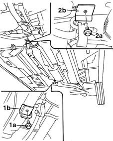
Proceed with removal - 4450B08 right rear wheel r r.
Proceed with removal - 7055B45 right hand rear supplementary wheel arch - r+r.
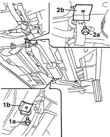
1. Undo bolt (1a) securing exhaust pipe support rear bracket securing bolts (1b).
2. Undo bolt (2a) securing exhaust pipe mount front bracket (2b).
Proceed with removal - 4450B08 right rear wheel r r.
Proceed with removal - 7055B45 right hand rear supplementary wheel arch - r+r.
1. Undo bolt (1a) securing exhaust pipe support rear bracket securing bolts (1b).
2. Undo bolt (2a) securing exhaust pipe mount front bracket (2b).
Proceed with removal - 4450B08 right rear wheel r r.
Proceed with removal - 7055B45 right hand rear supplementary wheel arch - r+r.
1. Undo bolt (1a) securing exhaust pipe support rear bracket securing bolts (1b).
2. Undo bolt (2a) securing exhaust pipe mount front bracket (2b).
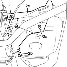
1. Open handbrake cable retaining collar.
2. Undo the nuts (2a), remove the clip (2b) and remove the central heat shield (2c).
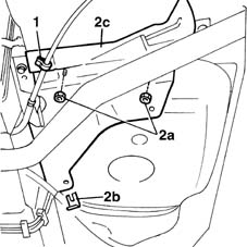
1. Open handbrake cable retaining collar.
2. Undo the nuts (2a), remove the clip (2b) and remove the central heat shield (2c).
1. Open handbrake cable retaining collar.
2. Undo the nuts (2a), remove the clip (2b) and remove the central heat shield (2c).
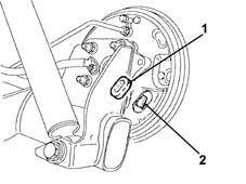
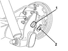
1. Remove the protective cover.
2. Disconnect the handbrake control cable from connection on the rear brake shoes.
1. Remove the protective covers.
2. Disconnect the handbrake control cable from connection on the rear brake shoes.
1. Remove the protective cover.
2. Disconnect the handbrake control cable from connection on the rear brake shoes.
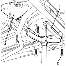
1. Arrange an appropriate stand under the fuel tank to support it.
2. Undo the fuel tank bracket retaining bolts.
3. Lower the fuel tank as necessary using the hydraulic jack.
Remove the fuel supply pipe after releasing it from the fastenings on the fuel tank.
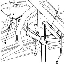
1. Arrange an appropriate stand under the fuel tank to support it.
2. Undo the fuel tank bracket retaining bolts.
3. Lower the fuel tank as necessary using the hydraulic jack.
Remove the fuel supply pipe after releasing it from the fastenings on the fuel tank.
1. Arrange an appropriate stand under the fuel tank to support it.
2. Undo the fuel tank bracket retaining bolts.
3. Lower the fuel tank as necessary using the hydraulic jack.
Remove the fuel supply pipe after releasing it from the fastenings on the fuel tank.
Refitting
Place the fuel supply pipe back in its housing and secure it to the underbody using the bands.
Place the fuel tank back in its housing using the hydraulic jack.
Tighten the bolts securing the fuel mounting brackets to the specified torque.
| Fastening | Component | Ø | Value (daNm) | |
|---|---|---|---|---|
| Bolt | FUEL TANK | M8 | (Bodyshell side) 3.2 ÷ 3.9 |
Remove the fuel tank support stand.
Connect the handbrake control cable to the fitting on the rear brake shoes.
Place the protective covers in their housings.
Refit the central heat shield in its seating, then secure it with the clip and nuts.
Secure the handbrake cables to the retaining band.
Tighten the bolt fixing the exhaust silencer front mounting bracket.
Undo exhaust pipe support front bracket securing bolts.
Proceed with refitting - 7055B45 right hand rear supplementary wheel arch - r+r.
Proceed with refitting - 4450B08 right rear wheel r r.
Fix the fuel supply pipe to the underbody fixings.
Place the protection back in its housing and secure it using the bolts.
Fix the fuel supply pipe to the front suspension beam using the fastenings.
Proceed with refitting - 4450B04 right front wheel r r.
Connect the rapid attachment for the fuel supply pipe.
Connect the electrical connection to the electric pump and fuel gauge sender unit.
Place the protective cover back in its housing and fix it using the bolts.
Put the floor trim back in its place.
Lower the rear seat cushion.
Connect the rapid attachment for the fuel supply pipe to the fuel manifold pipe and secure with the fastenings.
Proceed with refitting - 1048A10 air cleaner filtering element - replace.
Proceed with refitting - 3380A04 handbrake - check travel.
Proceed with refitting - 7040L22 REAR TRIM on TUNNEL -R.R..
Connect the negative (-) battery terminal.
Remove the car from the ramps.
Refitting
Place the fuel supply pipe back in its housing and secure it to the fuel tank using the bands.
Place the fuel tank back in its housing using the hydraulic jack.
Tighten the bolts securing the fuel mounting brackets to the specified torque.
| Fastening | Component | Ø | Value (daNm) | |
|---|---|---|---|---|
| Bolt | FUEL TANK | M8 | (Bodyshell side) 3.2 ÷ 3.9 |
Remove the fuel tank support stand.
Connect the handbrake control cable to the fitting on the rear brake shoes.
Place the protective covers in their housings.
Refit the central heat shield in its seating, then secure it with the clip and nuts.
Secure the handbrake cables to the retaining band.
Tighten the bolt fixing the exhaust silencer front mounting bracket.
Undo exhaust pipe support front bracket securing bolts.
Proceed with refitting - 7055B45 right hand rear supplementary wheel arch - r+r.
Proceed with refitting - 4450B08 right rear wheel r r.
Fix the fuel supply pipe to the underbody fixings.
Place the protection back in its housing and secure it using the bolts.
Fix the fuel supply pipe to the front suspension beam using the fastenings.
Proceed with refitting - 4450B04 right front wheel r r.
Connect the rapid attachment for the fuel supply pipe.
Connect the electrical connection to the electric pump and fuel gauge sender unit.
Place the protective cover back in its housing and fix it using the bolts.
Put the floor trim back in its place.
Lower the rear seat cushion.
Connect the rapid attachment for the fuel supply pipe to the fuel manifold pipe and secure with the fastenings.
Proceed with refitting - 1048A10 air cleaner filtering element - replace.
Proceed with refitting - 3380A04 handbrake - check travel.
Proceed with refitting - 7040L22 REAR TRIM on TUNNEL -R.R..
Connect the negative (-) battery terminal.
Remove the car from the ramps.
Parts & tools for this job For 2003 Lancia Ypsilon
- PARTFuel filterSearch: Lancia Ypsilon 2003 fuel filter
- TOOLFuel pressure test kitSearch: fuel pressure test kit
- TOOLFuel line disconnect toolSearch: fuel line disconnect tool
Links open Amazon search results in a new tab. As an Amazon Associate I earn from qualifying purchases.