300Tdi Defender

COOLING SYSTEM
3
DESCRIPTION AND OPERATION
COOLANT CIRCULATION
Operation
When the engine is started from cold the thermostat
(2) prevents coolant circulation through the radiator by
closing off the top hose (6). During the engine warm
up period the water pump (5) circulates coolant to the
cylinders in the crankcase and through separate ports
to the cylinder head. At the rear of the cylinder head a
proportion of the flow is diverted through a heater feed
pipe (16) to the matrix of the heater unit (15). The
coolant is then carried, via a heater return rail (14) and
hoses (7), back to the water pump. The remaining
coolant flows through a by-pass hose (9) at the
thermostat housing and back to the water pump to
complete the first cycle.
When the normal engine running temperature is
reached, the thermostat opens, closing off the by-pass
hose (9). Coolant is then circulated via the top hose
(6) and through the radiator, where it is cooled and
drawn from the radiator bottom hose (3) by the water
pump (5). The coolant circulation through the
crankcase and cylinder head remains the same.
Two bleed pipes (10) and (11) help control the system
pressure by purging excess air and coolant to the
expansion tank via the ’Y’piece ejector (12).
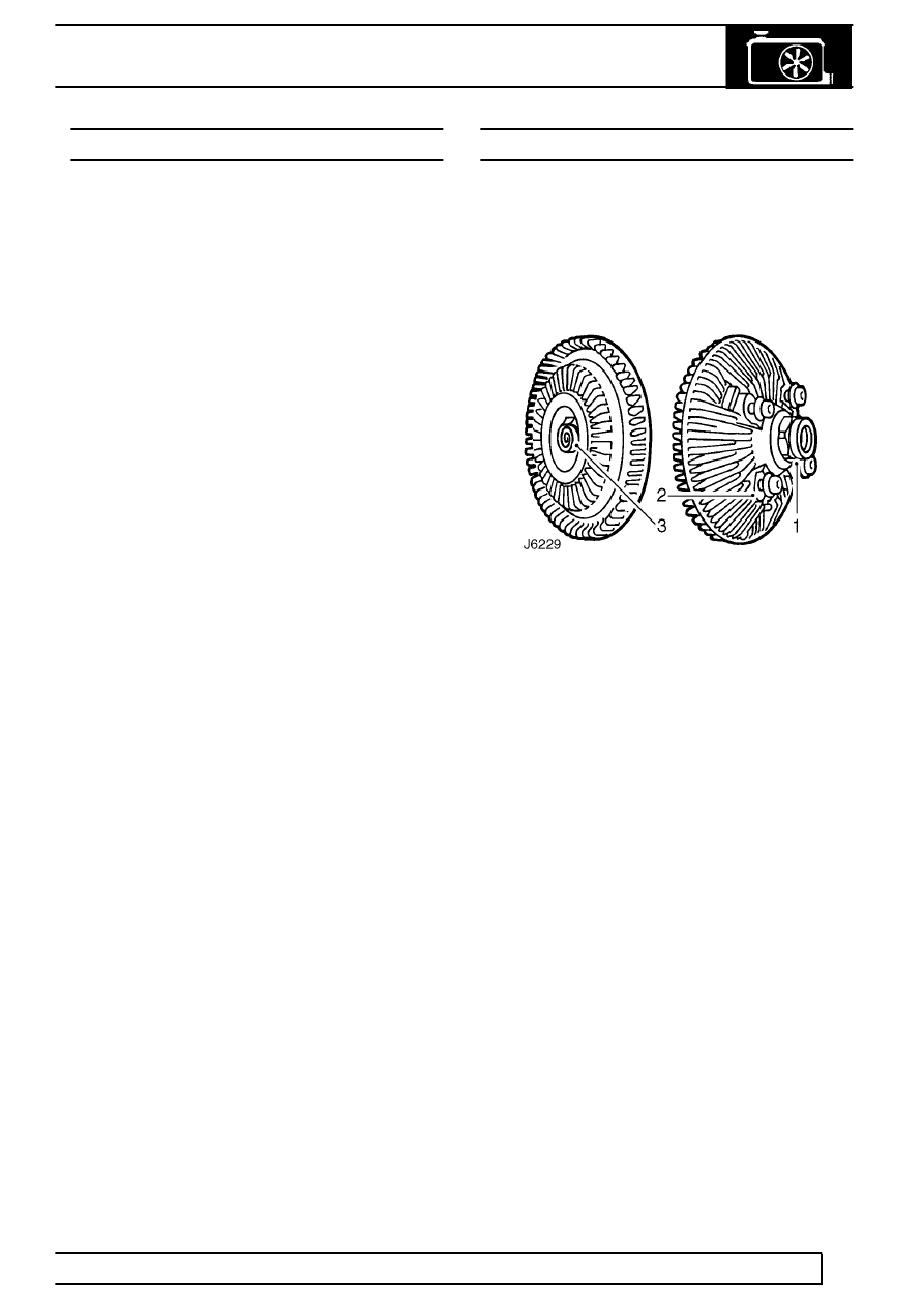
VISCOUS FAN
Description
The viscous drive unit for the engine cooling fan,
provides a means of controlling the speed of the fan
relative to the running temperature of the engine. The
viscous unit is a type of fluid coupling, which drives
the fan blades by means of ’silicone fluid’.
1. Input (drive) member
2. Output (driven) member
3. Sensing mechanism (bi-metal coil)
The fan drive has to be engaged only periodically,
between 5% and 10%, during normal operating
conditions, because the engine is cooled by ram air
for most of the time.
