300Tdi Defender

51
REAR AXLE AND FINAL DRIVE
2
OVERHAUL
CAUTION: To prevent permanent damage
to the gear carrier case, it must not be
over-stretched. Each flat on the turnbuckle
is numbered to enable a check to be made on the
amount turned. The maximum stretch permitted is
0,30 mm, equivalent to three flats.
15. Ease off adjuster and remove spreader.
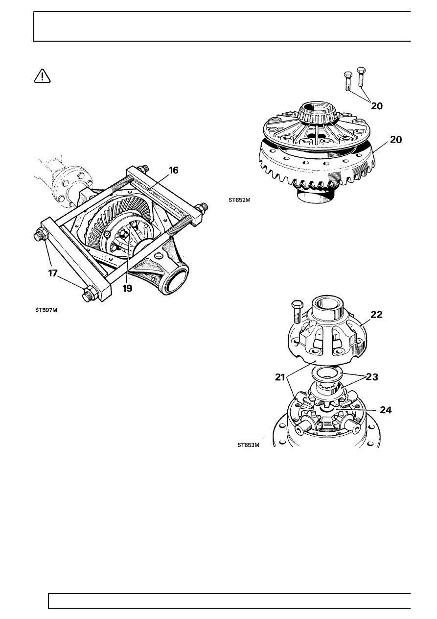
Using axle compressor LRT-51-503 (GKN 131)
16. Place tool on to differential casing, as illustrated,
with weld seam uppermost. Ensure that plates
rest squarely on differential machined surface
and end bars butt against edges of casing.
17. Tighten adjusting nuts by hand only, until all
slack is taken up.
18. Continue to tighten both nuts alternately with a
spanner, one flat at a time, to a maximum of
three flats.
19. Carefully lever-out differential assembly.
Dismantle differential
20. Add alignment marks between crown wheel and
differential case for reassembly purposes, then
remove fixings and withdraw crown wheel.
21. Note alignment markings on two differential
casings to ensure correct refitting, then remove
fixings.
22. Lift off upper case.
23. Withdraw upper differential wheel and thrust
washer.
24. Lift out cross-shaft and pinions.
