
Discovery II
AIR CONDITIONING
82-24
DESCRIPTION AND OPERATION
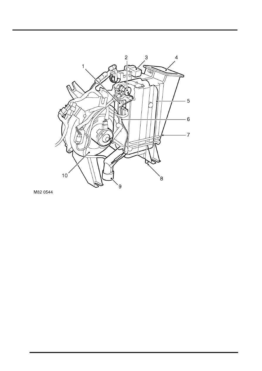
Rear evaporator/blower assembly
1 Resistor pack
2 Thermostatic expansion valve
3 Rear blower relay
4 Air outlet
5 Evaporator
6 Capillary tube
7 Housing
8 Condensate drain outlet
9 Refrigerant lines
10 Blower
The rear evaporator/blower assembly cools and dehumidifies air from the cabin and supplies it to the rear distribution
system. The unit is installed on the left side of the loadspace, behind the quarter trim. A grille in the quarter trim allows
air to flow from the loadspace into the evaporator/blower. Refrigerant lines for the evaporator and a condensate drain
tube are attached to the rear floor.
The evaporator and blower are installed in a common housing, which also incorporates the resistor pack for the
blower. A thermostatic expansion valve is integrated into the inlet refrigerant line. A rear blower relay is attached to
the top of the housing.
Evaporator
The evaporator absorbs heat from the recirculated air being supplied to the distribution ducts.
Thermostatic expansion valve
The thermostatic expansion valve meters the flow of refrigerant into the evaporator to match the heat load of the air
passing through the evaporator matrix. A capillary tube, attached to the outlet pipe of the evaporator and connected
to the thermostatic expansion valve, automatically adjusts the valve opening in relation to the refrigerant temperature
at the evaporator outlet.