Discovery II

BODY CONTROL UNIT
86-3-8
DESCRIPTION AND OPERATION
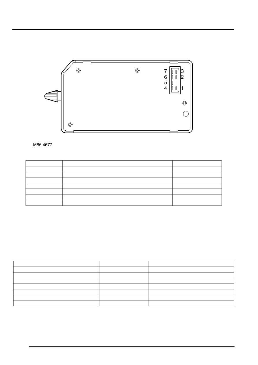
C0664 connector pin details
IDM inputs
The IDM inputs are communicated to the BCU using the serial datalink so that the BCU can perform the necessary
logic operations:
The V
in
for IDM digital signals are defined as follows:
l
Logic 1 when V
in
≥
8V.
l
Logic 0 when V
in
≤
2V.
IDM input voltages between 2 and 8 volts are indeterminate and cannot be guaranteed.
Pin No.
Description
Input/Output
1
Front left window down
Output
2
Front right window down
Output
3
Fuel flap release
Output
4
Front left window up
Output
5
Earth
-
6
Front right window up
Output
7
Battery power supply
Input
Description
Signal type
System
Inertia switch
Digital
Locking/ Unlocking/ Alarm
Side lamps
Digital
Exterior lighting
Headlamp dipped beam
Digital
Exterior lighting
Headlamp main beam daylight running lamps
Analogue
Exterior lighting
RH direction indicators current sense
Analogue
Direction indicators/ Hazards/ Alarm
LH direction indicators current sense
Analogue
Direction indicators/ Hazards/ Alarm
Front wiper park sense
Digital
Wipers and washers
