Discovery II

BRAKES
DESCRIPTION AND OPERATION
70-11
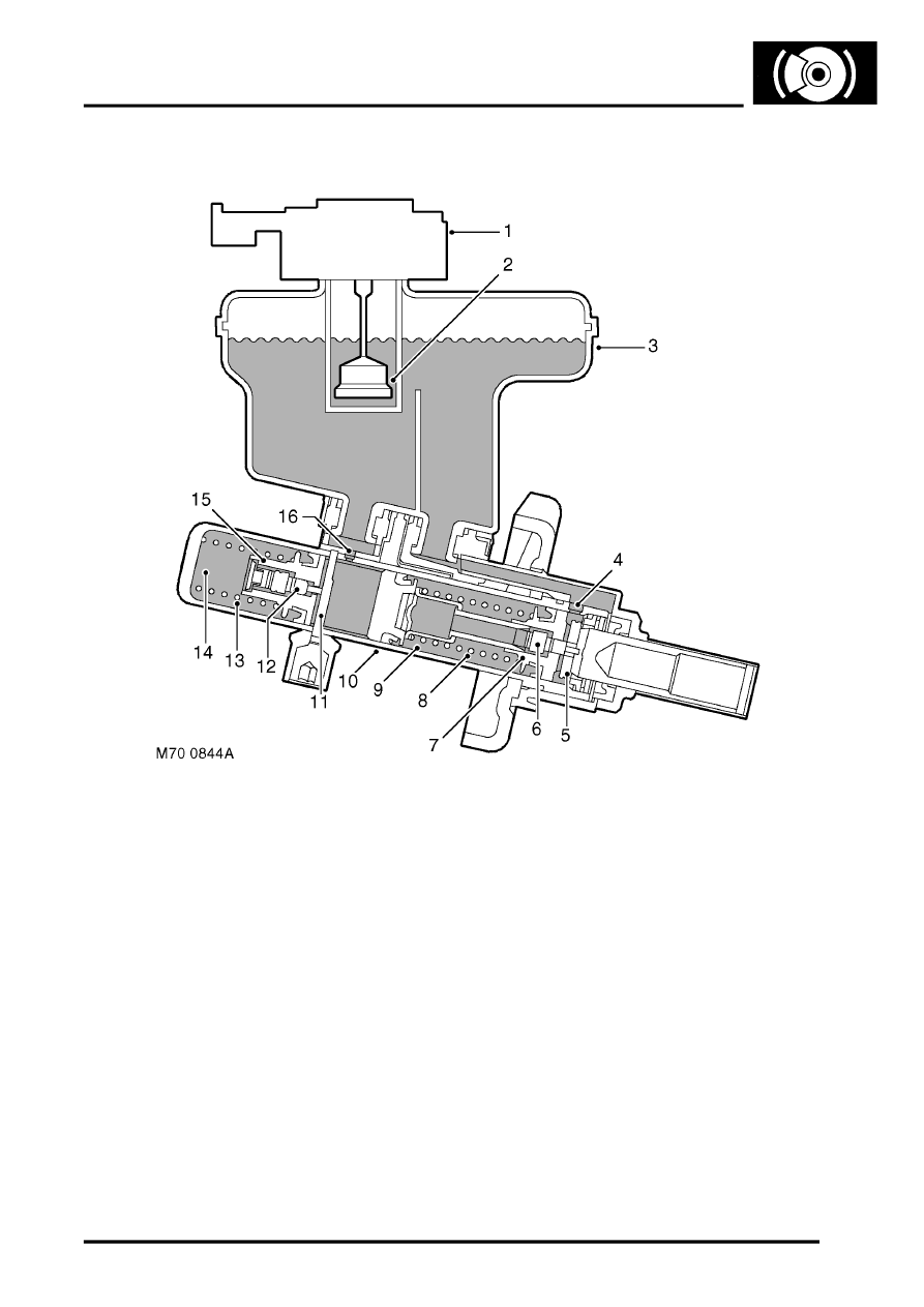
Master cylinder assembly
Section through master cylinder assembly
1 Reservoir filler cap
2 Switch float
3 Brake fluid reservoir
4 Primary feed hole
5 Valve pin
6 Primary centre valve
7 Primary piston
8 Primary spring
9 Pressure chamber
10 Cylinder
11 Valve pin
12 Secondary centre valve
13 Secondary spring
14 Pressure chamber
15 Secondary piston
16 Secondary feed hole
The master cylinder assembly produces hydraulic pressure to operate the brakes when the brake pedal is pressed.
The assembly is attached to the front of the brake servo assembly, and comprises a cylinder containing two pistons
in tandem. The rear piston produces pressure for the primary circuit and the front piston produces pressure for the
secondary circuit. A brake fluid reservoir is installed on top of the cylinder. The reservoir is internally divided to provide
an independent supply of fluid to each brake circuit, and so prevent a single fluid leak from disabling both primary and
secondary brake circuits. Should a failure occur in one circuit, the remaining circuit will still operate effectively,
although brake pedal travel and vehicle braking distances will increase. If the fluid level in the reservoir is too low, a
float operated switch in the reservoir filler cap connects an earth to the instrument pack, which illuminates the brake
warning lamp.
