
Discovery II
FRONT SUSPENSION
60-14
DESCRIPTION AND OPERATION
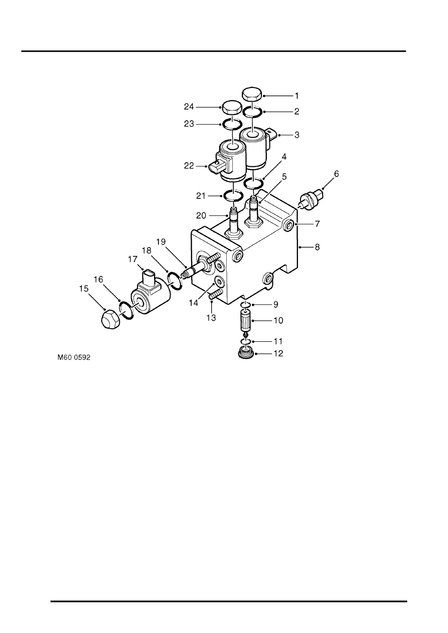
Valve block
1 Cap
2 'O' ring
3 Coil
4 'O' ring
5 Directional control valve 1 (extend)
6 Pressure transducer
7 Mounting bush 3 off
8 Valve block
9 'O' ring
10 High pressure filter
11 'O' ring
12 Cap
13 Stud 4 off
14 Pipe connections
15 Cap
16 'O' ring
17 Coil
18 'O' ring
19 Pressure control valve
20 Directional control valve 2 (retract)
21 'O' ring
22 Coil
23 'O' ring
24 Cap
The valve block directs hydraulic pressure to the actuators via solenoid operated directional control valves. A solenoid
operated pressure control valve regulates the required pressure to the actuators. The three valve solenoids are
controlled by signals received from the ACE ECU. A pressure transducer monitors the pressure delivered by the
pump. A replacable high pressure filter is installed into the lower face of the valve block and filters fluid before it
reaches the valves.
The valve block is located on the outside of the right hand chassis longitudinal. The valve block is secured to the
chassis with three bolts and rubber bushes. The rubber bushes isolate the valve block from the chassis, preventing
hydraulic noise from the valve block transmitting through the chassis and body.