
Discovery II
HEATING AND VENTILATION
80-4
DESCRIPTION AND OPERATION
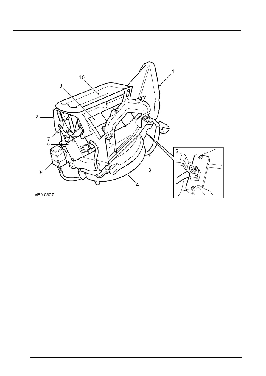
Air inlet duct
RH drive shown, LH drive similar
1 Air outlet
2 Resistor pack
3 Wiring harness
4 Blower
5 Blower relay
6 Recirculated air servo motor
7 Control flap operating mechanism
8 Recirculated air inlet
9 Recirculated air inlet
10 Fresh air inlet
The air inlet duct is installed behind the fascia, on the passenger's side. The air inlet duct is connected to the plenum
to provide the fresh air inlet. Two grilles in the air inlet duct provide recirculated air inlets from the cabin. Two control
flaps, operated by a servo motor, open and close the fresh and recirculated air inlets to control the source of incoming
air. Operation of the servo motor is controlled by a switch on the control panel.
The blower is installed between the air inlets and the outlet to the heater assembly, and consists of an open hub,
centrifugal fan powered by an electric motor. Operation of the blower is controlled by a slider switch on the control
panel, via a blower relay mounted on the air inlet duct and a resistor pack. The resistor pack is installed in the air outlet
from the blower fan, so that any heat generated is dissipated by the air flow. A wiring harness on the air inlet duct
connects the servo motor, blower motor, blower relay and resistor pack to the vehicle wiring.