
Discovery II
HEATING AND VENTILATION
DESCRIPTION AND OPERATION
80-5
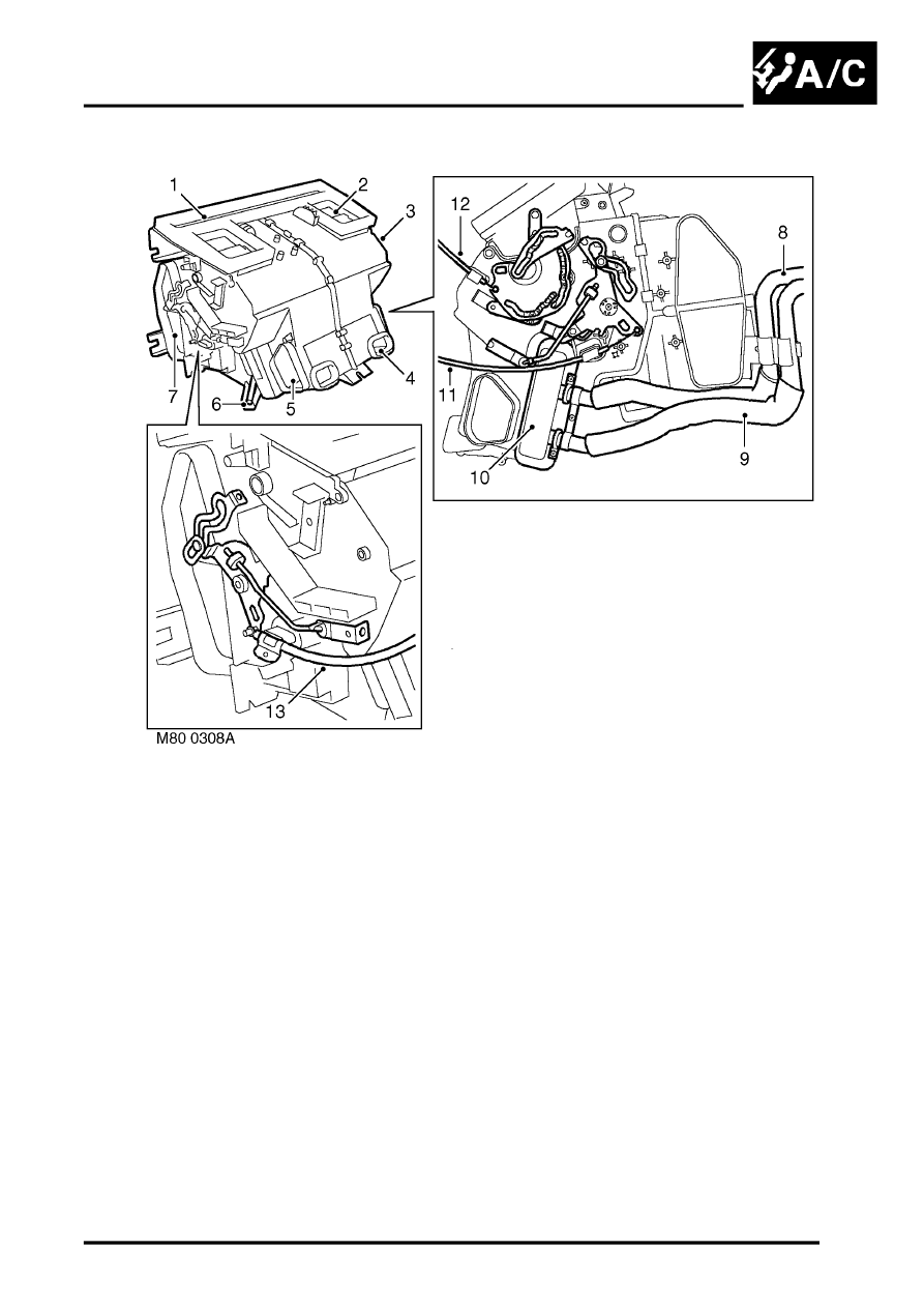
Heater assembly
1 Windscreen and side window air outlet
2 Face level air outlet
3 Casing
4 Rear footwell air outlet
5 Front footwell air outlet
6 Drain outlet
7 Air inlet
8 Engine coolant return
9 Engine coolant feed
10 Heater matrix
11 RH temperature control cable
12 Distribution control cable
13 LH temperature control cable
The heater assembly heats and distributes air as directed by selections made on the control panel. The assembly is
installed on the vehicle centre-line, between the fascia and the engine bulkhead. The heater assembly consists of a
casing, formed from a series of plastic moldings, which contains a heater matrix and control flaps. Internal passages
integrated into the casing guide the air through the casing and separate it into two flows, one for the LH outlets and
one for the RH outlets. Two drain outlets at the bottom of the casing connect to overboard drain tubes installed in the
sides of the transmission tunnel.
Heater matrix
The heater matrix provides the heat source to warm the air being supplied to the distribution outlets. The heater matrix
is an aluminium two pass, fin and tube heat exchanger, installed in the RH side of the casing. Two aluminium tubes
attached to the heater matrix extend through the engine bulkhead to connect the heater assembly to the engine
coolant system. When the engine is running, coolant is constantly circulated through the heater matrix by the engine
coolant pump. On diesel models, the coolant flow is assisted by an electric pump while the FBH system is active.