
Discovery II
HEATING AND VENTILATION
80-14
DESCRIPTION AND OPERATION
Coolant temperature control
When the ECU first enters the active mode, it initiates a start to full load combustion. Full load combustion continues
until the heat exchanger casing temperature reaches 60
°
C (140
°
F), when the ECU decreases the speed of the FBH
fuel pump and the combustion air fan to half speed, to produce part load combustion. The ECU maintains part load
combustion while the heat exchanger casing temperature remains between 54 and 65
°
C (129 and 149
°
F). If the heat
exchanger casing temperature decreases to 54
°
C (129
°
F), the ECU switches the system to full load combustion
again. If the heat exchanger casing temperature increases to 65
°
C (149
°
F), the ECU enters a control idle phase of
operation.
On entering the control idle phase, the ECU immediately switches the FBH fuel pump off, to stop combustion, and
starts a timer for the combustion air fan. After a 2 minute cooldown period, the ECU switches the combustion air fan
off and then remains in the control idle phase while the heat exchanger casing temperature remains above 59
°
C (138
°
F). If the heat exchanger casing temperature decreases to 59
°
C (138
°
F), within 15 minutes of the ECU entering the
control idle phase, the ECU initiates a start to part load combustion. If more than 15 minutes elapse before the heat
exchanger casing temperature decreases to 59
°
C (138
°
F), the ECU initiates a start to full load combustion.
In order to limit the build-up of carbon deposits on the glow plug/flame sensor, the ECU also enters the control idle
phase if the continuous part and/or full load combustion time exceeds 72 minutes. After the cooldown period, if the
heat exchanger casing is still in the temperature range that requires additional heat, the ECU initiates an immediate
restart to part or full load combustion, as appropriate.
Shutdown
The FBH system is de-activated when the alternator power supply to the FBH unit is disconnected, either by the
engine stopping or, if the ambient temperature increases to 5
°
C (41
°
F) or above, by the contacts in the air
temperature sensor opening. If the system is active when the alternator power supply is disconnected, the ECU de-
energises the FBH fuel pump to stop combustion, but continues operation of the combustion air fan and the circulation
pump to cool down the FBH unit. The cool down time depends on the combustion load at the time the alternator power
input is disconnected.
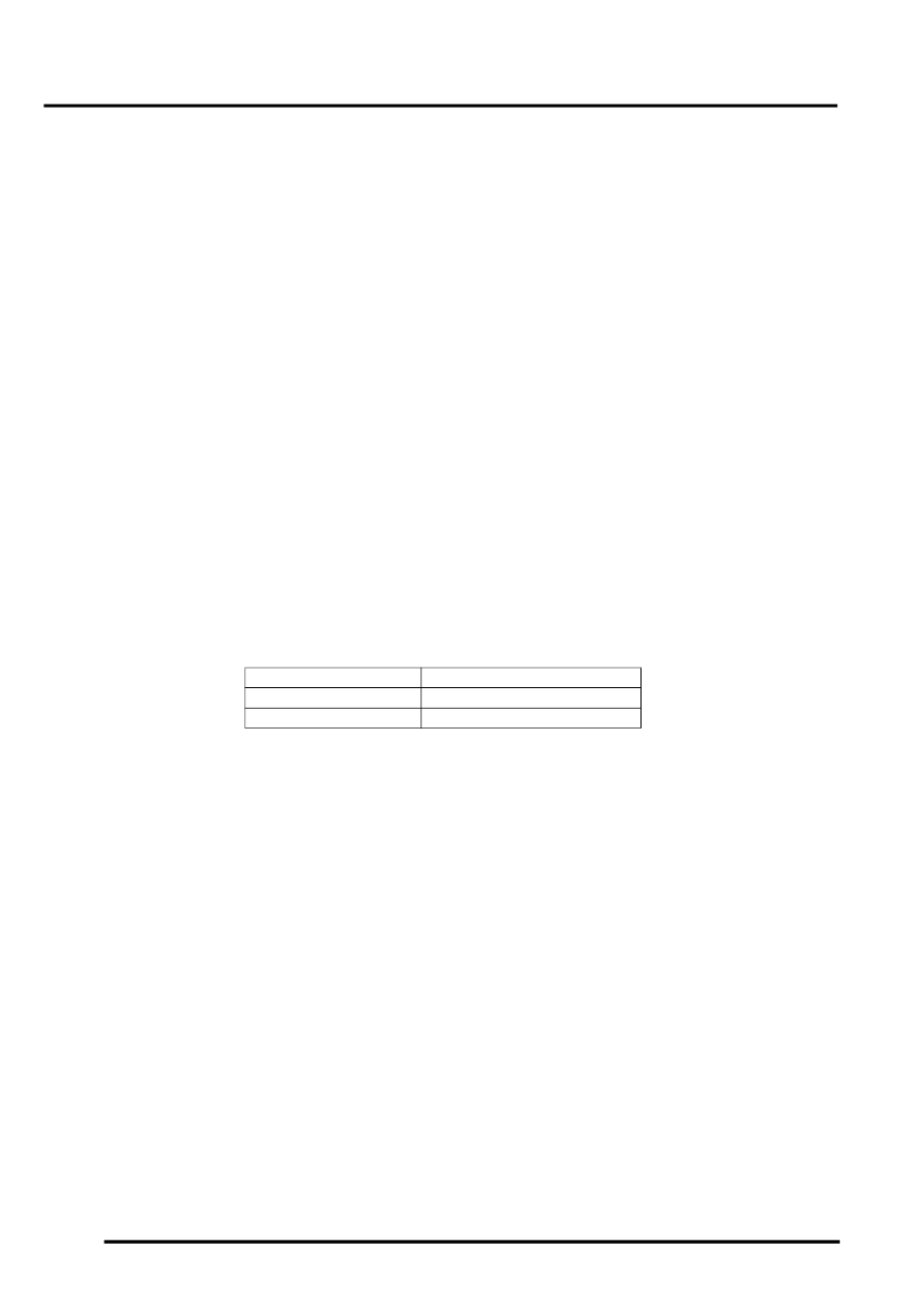
Cool down times
Diagnostics
The ECU in the FBH unit monitors the system for faults. Any faults detected are stored in a volatile memory in the the
ECU, which can be interrogated by Testbook. A maximum of three faults and associated freeze frame data can be
stored at any one time. If a further fault is detected, the oldest fault is overwritten by the new fault.
The ECU also incorporates an error lockout mode of operation that inhibits system operation to prevent serious faults
from causing further damage to the system. In the error lockout mode, the ECU immediately stops the FBH fuel pump,
and stops the combustion air fan and circulation pump after a cool down time of approximately 2 minutes. Error lockout
occurs for start sequence failures and/or combustion flameouts, heat exchanger casing overheat and out of limit input
voltage. The error lockout mode can be cleared using Testbook, or by disconnecting the battery power supply for a
minimum of 10 seconds.
Start failure/flameout. If a start sequence fails to establish combustion, or a flameout occurs after combustion is
established, the ECU immediately initiates another start sequence. The start failure or flameout is also recorded by
an event timer in the ECU. The event timer is increased by one after each start failure or flameout, and decreased by
one if a subsequent start is successful. If the event timer increases to three (over any number of drive cycles), the
ECU enters the error lockout mode.
Heat exchanger casing overheat. To protect the system from excessive temperatures, the ECU enters the error
lockout mode if the heat exchanger casing temperature exceeds 105
°
C (221
°
F).
Out of limit voltage. The ECU enters the error lockout mode if the battery or alternator power input is less than 10.5
±
0.3 V for more than 20 seconds, or more than 15.5
±
0.5 V for more than 6 seconds.
Combustion load
Cool down time, seconds
Part
100
Full
175