
Discovery II
IN CAR ENTERTAINMENT
86-6-2
DESCRIPTION AND OPERATION
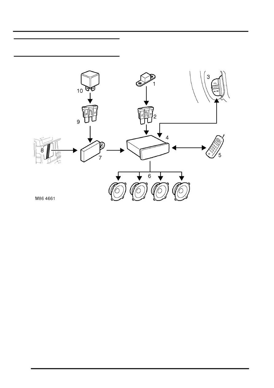
Base and mid line ICE system control
diagram
1 Fusible link
2 Battery power supply fuse
3 Remote radio control switches (if fitted)
4 Radio cassette
5 Telephone system interface
6 Speakers
7 Amplifier AM/FM aerial
8 AM/FM aerial
9 Auxiliary power supply fuse
10 Auxiliary relay